ECD SYSTEM (w/o EGR Cooler Bypass Valve) MIL Circuit
DESCRIPTION
If the ECM detects a malfunction, the MIL illuminates. The ECM then records the DTC in its memory.
WIRING DIAGRAM
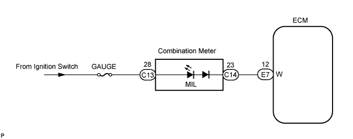
INSPECTION PROCEDURE
Note
If the ECM is replaced, the new ECM needs initialization Click here.
PROCEDURE
-
CHECK MIL
Tech Tips
Use the table below to troubleshoot each problem symptom.
Reference Condition Proceed to MIL remains ON A MIL is not illuminated B
B 
CHECK IF MIL ILLUMINATES Click here
A 
-
CHECK IF MIL TURNS OFF
-
Connect the intelligent tester to the DLC3.
-
Turn the ignition switch ON and turn the tester ON.
-
Select the following menu items: Powertrain / Engine and ECT / DTC.
-
Check if DTCs have been stored. Take notes if there are DTCs.
-
Select the following menu items: Powertrain / Engine and ECT / DTC / Clear.
-
Clear the DTC(s) Click here.
-
Check if the MIL turns OFF.
OK MIL turns OFF.
OK 
GO TO DTC CHART
NG
-
-
CHECK HARNESS AND CONNECTOR
-
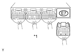
Text in Illustration *1 ECM Connector Disconnect the E7 ECM connector.
-
Turn the ignition switch ON.
-
Check that the MIL does not illuminate.
OK MIL does not illuminate. -
Reconnect the ECM connector.
NG
REPAIR OR REPLACE HARNESS OR CONNECTOR
OK 
REPLACE ECM
-
-
CHECK IF MIL ILLUMINATES
-
Check if the MIL illuminates when the ignition switch is turned ON.
OK MIL illuminates.
OK
END
NG
-
-
CHECK THAT ENGINE STARTS
-
Turn the ignition switch ON.
-
Start the engine.
Result Result Proceed to Engine starts A Engine does not start*
B Tech Tips
*: The intelligent tester cannot communicate with the ECM.
B
GO TO VC OUTPUT CIRCUIT Click here
A
-
-
CHECK COMBINATION METER ASSEMBLY (MIL CIRCUIT)
OK Combination meter circuit is normal.
NG
REPAIR OR REPLACE COMBINATION METER ASSEMBLY
OK
REPAIR OR REPLACE HARNESS OR CONNECTOR (COMBINATION METER - ECM)