ECD SYSTEM (w/o EGR Cooler Bypass Valve) Starter Signal Circuit
DESCRIPTION
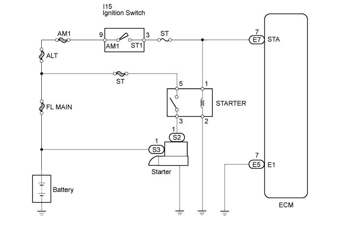
While the engine is being cranked, current flows from terminal ST2 of the ignition switch to the ST fuse and also flows to terminal STA of the ECM (STA signal).
WIRING DIAGRAM
INSPECTION PROCEDURE
Tech Tips
This chart is based on the premise that the engine can crank normally. If the engine cannot crank normally, proceed to the problem symptoms table Click here.
Note
If the ECM is replaced, the new ECM needs initialization Click here.
PROCEDURE
-
READ VALUE USING INTELLIGENT TESTER (STARTER SIGNAL)
-
Connect the intelligent tester to the DLC3.
-
Turn the ignition switch ON and turn the tester ON.
-
Select the following menu items: Powertrain / Engine and ECT / Data List / Starter Signal.
-
Read the values.
Standard Ignition Switch Position Starter SIG ON OFF START ON
OK 
PROCEED TO NEXT SUSPECTED AREA SHOWN IN PROBLEM SYMPTOMS TABLE
NG 
-
-
CHECK HARNESS AND CONNECTOR (ECM - ST RELAY)
-
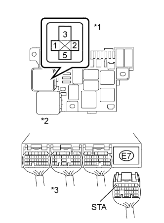
Text in Illustration *1 ST Relay *2 R/B No. 2 *3 ECM Connector Disconnect the E7 ECM connector.
-
Remove the ST relay from the R/B No. 2.
-
Measure the resistance of the wire harness side connectors.
Standard resistance Tester Connection Specified Condition Relay block ST relay terminal 1 - E7-7 (STA) Below 1 Ω Relay block ST relay terminal 1 or E7-7 (STA) - Body ground 10 kΩ or higher -
Reconnect the ECM connector.
-
Reinstall the ST relay
NG
REPAIR OR REPLACE HARNESS OR CONNECTOR
OK 
REPLACE ECM
-