ECD SYSTEM (w/o EGR Cooler Bypass Valve) ECM Power Source Circuit
DESCRIPTION
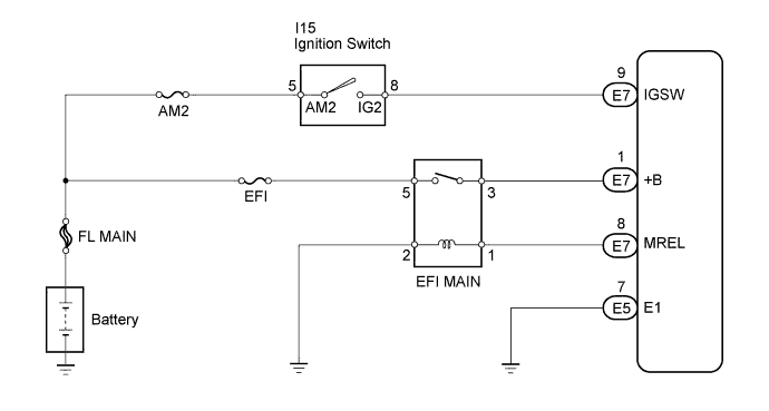
When the ignition switch is turned ON, the battery voltage is applied to terminal IGSW of the ECM. The ECM "MREL" output signal causes a current to flow to the coil, closing the contacts of the MAIN relay and supplying power to terminal +B of the ECM.
WIRING DIAGRAM
INSPECTION PROCEDURE
Note
After replacing the ECM, the new ECM needs registration Click here and initialization Click here.
PROCEDURE
-
INSPECT ECM (+B VOLTAGE)
-
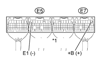
Text in Illustration *1 ECM Connector Turn the ignition switch ON.
-
Measure the voltage of the ECM connectors.
Standard voltage Tester Connection Specified Condition E7-1 (+B) - E5-7 (E1) 11 to 14 V
OK 
PROCEED TO NEXT CIRCUIT INSPECTION SHOWN IN PROBLEM SYMPTOMS TABLE
NG 
-
-
CHECK HARNESS AND CONNECTOR (ECM - BODY GROUND)
-
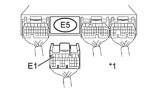
Text in Illustration *1 ECM Connector Disconnect the E5 ECM connector.
-
Measure the resistance of the wire harness side connector.
Standard resistance Tester Connection Specified Condition E5-7 (E1) - Body ground Below 1 Ω -
Reconnect the ECM connector.
NG
REPAIR OR REPLACE HARNESS OR CONNECTOR
OK
-
-
INSPECT ECM (IGSW VOLTAGE)
-
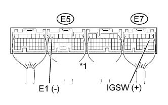
Text in Illustration *1 ECM Connector Turn the ignition switch ON.
-
Measure the voltage of the ECM connectors.
Standard voltage Tester Connection Specified Condition E7-9 (IGSW) - E5-7 (E1) 11 to 14 V
OK 
INSPECT FUSE (EFI FUSE) Click here
NG
-
-
INSPECT IGNITION SWITCH ASSEMBLY
-
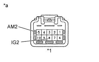
Text in Illustration *1 Ignition Switch Connector *a Component Side Disconnect the I15 ignition switch connector.
-
Measure the resistance of the ignition switch.
Standard resistance Tester Connection Switch Condition Specified Condition 5 (AM2) - 8 (IG2) LOCK 10 kΩ or higher 5 (AM2) - 8 (IG2) ON Below 1 Ω -
Reconnect the ignition switch connector.
NG
REPLACE IGNITION SWITCH ASSEMBLY
OK
-
-
INSPECT ECM (MREL VOLTAGE)
-
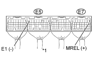
Text in Illustration *1 ECM Connector Turn the ignition switch ON.
-
Measure the voltage of the ECM connectors.
Standard voltage Tester Connection Specified Condition E7-8 (MREL) - E5-7 (E1) 11 to 14 V
NG
REPLACE ECM
OK
-
-
INSPECT FUSE (EFI FUSE)
-
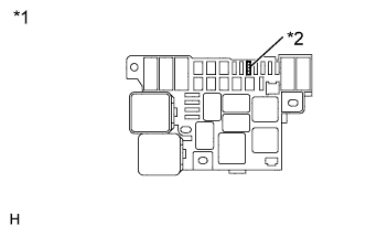
Text in Illustration *1 R/B No. 2 *2 EFI Remove the EFI fuse from the R/B No. 2.
-
Measure the resistance of the fuse.
Standard resistance Below 1 Ω -
Reinstall EFI fuse.
NG
CHECK FOR SHORT IN ALL HARNESSES AND CONNECTORS CONNECTED TO FUSE AND REPLACE FUSE
OK
-
-
INSPECT EFI MAIN RELAY
-
Remove the EFI MAIN relay from the R/B No, 2.
-
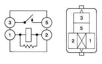
Inspect the EFI MAIN relay.
Standard resistance Tester Connection Specified Condition 3 - 5 10 kΩ or higher Below 1 Ω (Apply battery voltage to terminals 1 and 2) -
Reinstall the EFI MAIN relay.
NG
REPLACE EFI MAIN RELAY
OK
-
-
CHECK HARNESS AND CONNECTOR (EFI MAIN RELAY - ECM)
-
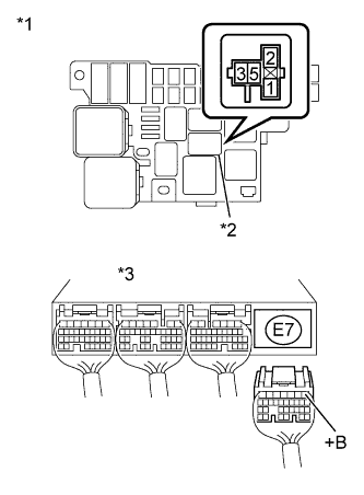
Text in Illustration *1 R/B No. 2 *2 EFI MAIN Relay *3 ECM Connector Remove the EFI MAIN relay from the R/B No. 2.
-
Disconnect the E7 ECM connector.
-
Measure the resistance of the wire harness side connectors.
Standard resistance Tester Connection Specified Condition EFI MAIN relay terminal 3 - E7-1 (+B) Below 1 Ω EFI MAIN relay terminal 3 or E7-1 (+B) - Body ground 10 kΩ or higher -
Reinstall the EFI MAIN relay.
-
Reconnect the ECM connector.
NG
REPAIR OR REPLACE HARNESS OR CONNECTOR (EFI MAIN RELAY - ECM)
OK 
REPAIR OR REPLACE HARNESS OR CONNECTOR (+B TERMINAL OF ECM - BATTERY POSITIVE TERMINAL)
-