ECD SYSTEM (w/o EGR Cooler Bypass Valve), Diagnostic DTC:P0500
| DTC Code | DTC Name |
|---|---|
| P0500 | Vehicle Speed Sensor "A" |
DESCRIPTION
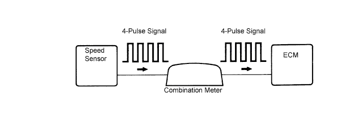
The vehicle speed sensor outputs a 4-pulse signal for every revolution of the rotor shaft, which is rotated by the transmission output shaft via the driven gear. After this signal is converted into a more precise rectangular waveform by the waveform shaping circuit inside the combination meter, it is then transmitted to the ECM. The ECM determines the vehicle speed based on the frequency of these pulse signals.
| DTC No. | DTC Detection Condition | Trouble Area |
|---|---|---|
| P0500 | Following conditions (a), (b), (c) and (d) met for 8 seconds or more: (2 trip detection logic)
|
|
| Following conditions (a), (b) and (c) met for 5.4 seconds or more: (2 trip detection logic)
|
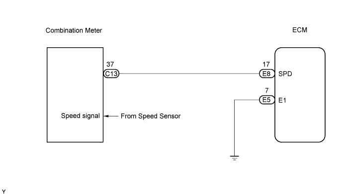
WIRING DIAGRAM
INSPECTION PROCEDURE
Note
If the ECM is replaced, the new ECM needs initialization Click here.
Tech Tips
Read freeze frame data using the intelligent tester. Freeze frame data records the engine conditions when a malfunction is detected. When troubleshooting, freeze frame data can help determine if the vehicle was running or stopped, if the engine was warmed up or not, and other data from the time the malfunction occurred.
PROCEDURE
-
CHECK COMBINATION METER ASSEMBLY (OPERATION OF SPEEDOMETER)
-
Drive the vehicle.
-
Check the speedometer reading in the combination meter.
Tech Tips
If the vehicle speed sensor signal is inaccurate, the speedometer will show abnormal readings.
OK Speedometer operates normally.
NG 
CHECK SPEEDOMETER CIRCUIT (INCLUDING SPEED SENSOR)
OK 
-
-
READ VALUE USING INTELLIGENT TESTER (VEHICLE SPEED)
-
Connect the intelligent tester to the DLC3.
-
Start the engine and turn the tester ON.
-
Select the following menu items: Powertrain / Engine / Data List / Vehicle Speed.
-
While the vehicle is running, check the vehicle speed at an engine speed of 2,000 rpm or more.
OK Same value as actual vehicle speed.
OK
CHECK FOR INTERMITTENT PROBLEMS
NG
-
-
INSPECT ECM (SPD SIGNAL)
-
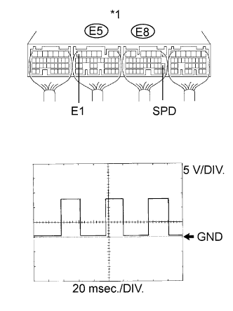
Text in Illustration *1 ECM Connector While idling the engine, check the waveform of the ECM connectors using an oscilloscope.
-
Shift the lever to the neutral position.
-
Jack up the vehicle.
-
Turn the ignition switch ON.
-
Measure the voltage of the ECM connectors as the rear wheels are turned slowly.
OK Tester Connection Specified Condition E8-17 (SPD) - E5-7 (E1) Correct waveform is as shown Tool Setting Condition 5 V/DIV., 20 msec./DIV. Turn the rear wheel slowly Tech Tips
When the wheel is turning slowly, voltage is output intermittently.
-
NG
REPAIR OR REPLACE HARNESS OR CONNECTOR
OK 
REPLACE ECM
-