ECD SYSTEM (w/o EGR Cooler Bypass Valve), Diagnostic DTC:P0405, P0406
| DTC Code | DTC Name |
|---|---|
| P0405 | Exhaust Gas Recirculation Sensor "A" Circuit Low |
| P0406 | Exhaust Gas Recirculation Sensor "A" Circuit High |
DESCRIPTION
The EGR valve position sensor is mounted on the EGR valve and used for detecting the lift amount of the valve. The lift amount detected by the sensor is provided to the ECM as feedback. The ECM then regulates the lift amount of the valve in accordance with engine running conditions.
| DTC No. | DTC Detection Condition | Trouble Area |
|---|---|---|
| P0405 | EGR valve position sensor output voltage is less than 0.1 V for more than 5 seconds (1 trip detection logic) |
|
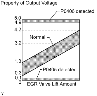
| P0406 | EGR valve position sensor output voltage is more than 4.9 V for more than 5 seconds (1 trip detection logic) |
|
MONITOR DESCRIPTION
When output voltage of the EGR valve position sensor deviates from the normal operating range of 0.1 to 4.9 V for more than 0.5 seconds, the ECM interprets this as a malfunction of the sensor circuit, and illuminates the MIL.
WIRING DIAGRAM
Refer to DTC P0400 Click here.
INSPECTION PROCEDURE
Note
After replacing the ECM, the new ECM needs registration Click here and initialization Click here.
Tech Tips
Read freeze frame data using the intelligent tester. The ECM records vehicle and driving condition information as freeze frame data the moment a DTC is stored. When troubleshooting, freeze frame data can help determine if the vehicle was running or stopped, if the engine was warmed up or not, and other data from the time the malfunction occurred.
PROCEDURE
-
CHECK TERMINAL VOLTAGE (EGR VALVE POSITION SENSOR CONNECTOR)
-
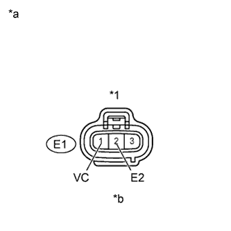
Text in Illustration *1 EGR Valve Position Sensor Connector *a Wire Harness Side *b Front View Disconnect the E1 EGR valve position sensor connector.
-
Turn the ignition switch ON.
-
Measure the voltage of the wire harness side connector.
Standard voltage Tester Connection Specified Condition E1-1 (VC) - E1-2 (E2) 4.5 to 5.5 V -
Reconnect the EGR valve position sensor connector.
NG 
CHECK HARNESS AND CONNECTOR (EGR VALVE POSITION SENSOR - ECM) Click here
OK 
-
-
INSPECT EGR VALVE POSITION SENSOR
-
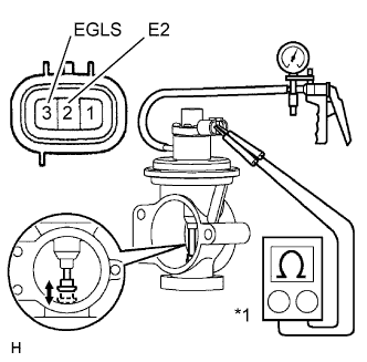
Text in Illustration *1 Ohmmeter Disconnect the EGR valve position sensor connector.
-
Create a vacuum in the diaphram chamber.
-
Measure the resistance of the EGR valve position sensor when the valve is fully opened and fully closed.
Standard resistance Tester Connection EGR Valve Condition Condition Specified Condition 3 (EGLS) - 2 (E2) Fully opened 20°C (68°F) 2.0 to 7.0 kΩ 3 (EGLS) - 2 (E2) Fully closed 20°C (68°F) 0.1 to 2.5 kΩ -
Reconnect the EGR valve position sensor connector.
NG 
REPLACE EGR VALVE POSITION SENSOR
OK
-
-
CHECK HARNESS AND CONNECTOR (EGR VALVE POSITION SENSOR - ECM)
-
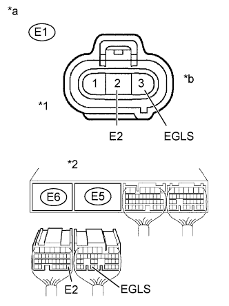
Text in Illustration *1 EGR Valve Position Sensor Connector *2 ECM Connector *a Wire Harness Side *b Front View Disconnect the E1 EGR valve position sensor connector.
-
Disconnect the E5 and E6 ECM connectors.
-
Check the resistance.
Standard resistance (Check for open) Tester Connection Specified Condition E1-3 (EGLS) - E5-33 (EGLS) Below 1 Ω E2 (E1-2) - E2 (E6-28) Below 1 Ω Standard resistance (Check for short) Tester Connection Specified Condition E1-3 (EGLS) or E5-33 (EGLS)- Body ground 10 kΩ or higher -
Reconnect the EGR valve position sensor connector.
-
Reconnect the ECM connectors.
NG
REPAIR OR REPLACE HARNESS OR CONNECTOR
OK 
REPLACE ECM
-