ECD SYSTEM (w/o EGR Cooler Bypass Valve), Diagnostic DTC:P0122, P0123
| DTC Code | DTC Name |
|---|---|
| P0122 | Throttle / Pedal Position Sensor / Switch "A" Circuit Low Input |
| P0123 | Throttle / Pedal Position Sensor / Switch "A" Circuit High Input |
DESCRIPTION
Tech Tips
-
These troubleshooting procedures are for the throttle position sensor.
-
This electrical throttle system does not use a throttle cable.
-
This throttle valve position sensor is a non-contact type.
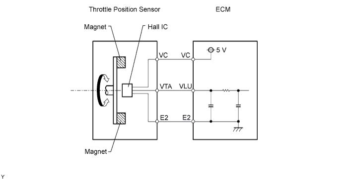
The throttle position sensor is mounted on the diesel throttle body and detects the opening angle of the throttle valve. This sensor is electronically controlled and uses Hall-effect elements.
The ECM judges the vehicle's driving conditions from the signals input to its VLU terminal. The data is one of the conditions for EGR control, etc.
| DTC No. | DTC Detection Condition | Trouble Area |
|---|---|---|
| - | Condition of DTC P0122 or P0123 continues for 5 seconds (open or short in throttle position sensor circuit) | - |
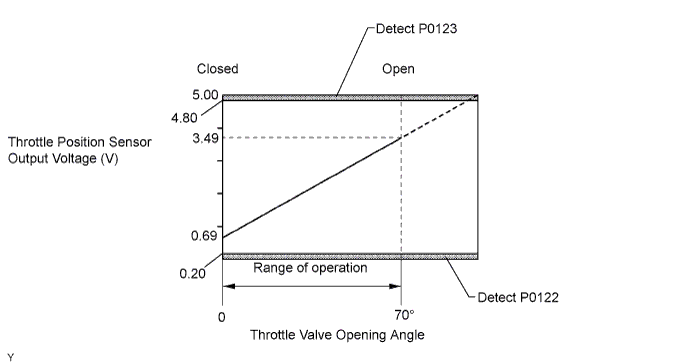
| P0122 | Throttle position sensor output (VLU) is less than 0.2 V (1 trip detection logic) |
|
| P0123 | Throttle position sensor output (VLU) is more than 4.8 V (1 trip detection logic) |
|
MONITOR DESCRIPTION
When the output voltage of the throttle position sensor deviates from the normal operating range (between 0.2 V and 4.8 V) for more than 3 seconds, the ECM interprets this as a malfunction of the sensor circuit and illuminates the MIL.
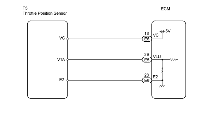
WIRING DIAGRAM
INSPECTION PROCEDURE
Tech Tips
-
If DTCs related to different systems that have terminal E2 as the ground terminal are output simultaneously, terminal E2 may have an open circuit.
-
Read freeze frame data using the intelligent tester. Freeze frame data records the engine conditions when a malfunction is detected. When troubleshooting, freeze frame data can help determine if the vehicle was running or stopped, if the engine was warmed up or not, and other data from the time the malfunction occurred.
Note
If the ECM is replaced, the new ECM needs initialization Click here.
PROCEDURE
-
CHECK HARNESS AND CONNECTOR (THROTTLE POSITION SENSOR - ECM)
-
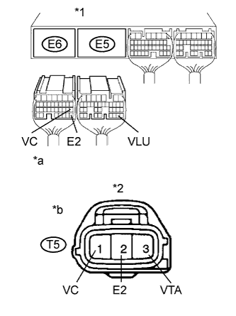
Text in Illustration *1 ECM Connector *2 Throttle Position Sensor Connector *a Wire Harness Side *b Front View Disconnect the E5 and E6 ECM connectors.
-
Disconnect the T5 throttle position sensor connector.
-
Check the resistance.
Standard resistance (Check for open) Tester Connections Specified Conditions E6-18 (VC) - T5-1 (VC) Below 1 Ω E5-29 (VLU) - T5-3 (VTA) Below 1 Ω E6-28 (E2) - T5-2 (E2) Below 1 Ω Standard resistance (Check for short) Tester Connections Specified Conditions E6-18 (VC) or T5-1 (VC) - Body ground 10 kΩ or higher E5-29 (VLU) or T5-3 (VTA) - Body ground 10 kΩ or higher -
Reconnect the throttle position sensor connector.
-
Reconnect the ECM connector.
NG 
REPAIR OR REPLACE HARNESS OR CONNECTOR
OK 
-
-
INSPECT ECM TERMINAL VOLTAGE (VC VOLTAGE)
-
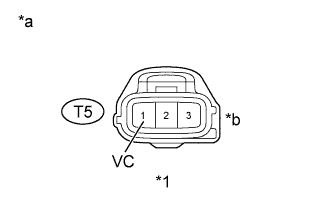
Text in Illustration *1 Throttle Position Sensor Connector *a Wire Harness Side *b Front View Disconnect the T5 throttle position sensor connector.
-
Turn the ignition switch ON.
-
Measure the voltage between the terminal of the wire harness side connector and body ground.
Standard voltage Tester Connections Specified Conditions T5-1 (VC) - Body ground 4.5 to 5.5 V -
Reconnect the throttle position sensor connector.
NG
REPLACE ECM
OK
-
-
REPLACE DIESEL THROTTLE BODY ASSEMBLY (THROTTLE VALVE)
-
Replace the diesel throttle body assembly.
NEXT
-
-
CHECK WHETHER DTC OUTPUT RECURS (DTC P0122 AND/OR P0123)
-
Clear the DTCs Click here.
-
Start the engine.
-
Let the engine idle for 60 seconds.
-
Repeat quick engine revving to 2,500 rpm for 30 seconds.
-
Read the DTCs.
Result Display (DTC Output) Proceed To P0122 and/or P0123 A No output B
B
SYSTEM IS OK
A 
REPLACE ECM
-