ECD SYSTEM (w/o EGR Cooler Bypass Valve), Diagnostic DTC:P0115, P0117, P0118
| DTC Code | DTC Name |
|---|---|
| P0115 | Engine Coolant Temperature Circuit |
| P0117 | Engine Coolant Temperature Circuit Low Input |
| P0118 | Engine Coolant Temperature Circuit High Input |
DESCRIPTION
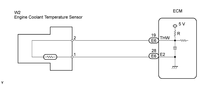
A thermistor is built into the Engine Coolant Temperature (ECT) sensor and it changes its resistance value according to the engine coolant temperature.
The structure of the sensor and connection to the ECM is the same as the intake air temperature sensor.
Tech Tips
If the ECM detects the DTC P0115, P0117, or P0118, it operates the fail-safe function in which the ECT is assumed to be 80°C (176°F).
| DTC No. | DTC Detection Condition | Trouble Area |
|---|---|---|
| P0115 | Open or short in ECT sensor circuit for 0.5 seconds (1 trip detection logic) |
|
| P0117 | Short in ECT sensor circuit for 0.5 seconds (sensor resistance value less than 79 Ω) (1 trip detection logic) |
|
| P0118 | Open in ECT sensor circuit for 0.5 seconds (sensor resistance value more than 156 kΩ) (1 trip detection logic) |
|
Tech Tips
When DTC P0115, P0117, and/or P0118 is detected, check the engine coolant temperature by entering the following menus on the intelligent tester: Powertrain / Engine and ECT / Data List / Coolant Temp.
| Temperature Displayed | Malfunction |
|---|---|
| -40°C (-40°F) | Open circuit |
| 140°C (284°F) or more | Short circuit |
WIRING DIAGRAM
INSPECTION PROCEDURE
Tech Tips
-
If other DTCs relating to different systems that have terminal E2 as the ground terminal are output simultaneously, terminal E2 may have an open circuit.
-
Read freeze frame data using an intelligent tester. Freeze frame data record the engine condition when malfunctions are detected. When troubleshooting, freeze frame data can help determine if the vehicle was moving or stationary, if the engine was warmed up or not, if the air-fuel ratio was lean or rich, and other data, from the time the malfunction occurred.
Note
If the ECM is replaced, the new ECM needs initialization Click here.
PROCEDURE
-
READ VALUE USING INTELLIGENT TESTER (ENGINE COOLANT TEMPERATURE)
-
Connect an intelligent tester to the DLC3.
-
Turn the ignition switch ON and turn the tester ON.
-
Select the following menu items: Powertrain / Engine and ECT / Data List / Coolant Temp.
-
Read the value displayed on the tester.
Standard 75°C to 95°C (167°F to 203°F) with warm engine. Result Temperature Displayed Proceed To -40°C (-40°F) A 140°C (284°F) or higher B 80°C to 100°C (176°F to 212°F) C Tech Tips
-
If there is an open circuit, the intelligent tester indicates -40°C (-40°F).
-
If there is a short circuit, the intelligent tester indicates 140°C (284°F) or higher.
-
B 
READ VALUE USING INTELLIGENT TESTER (CHECK FOR SHORT IN WIRE HARNESS) Click here
C 
CHECK FOR INTERMITTENT PROBLEMS
A 
-
-
READ VALUE USING INTELLIGENT TESTER (CHECK FOR OPEN IN WIRE HARNESS)
-
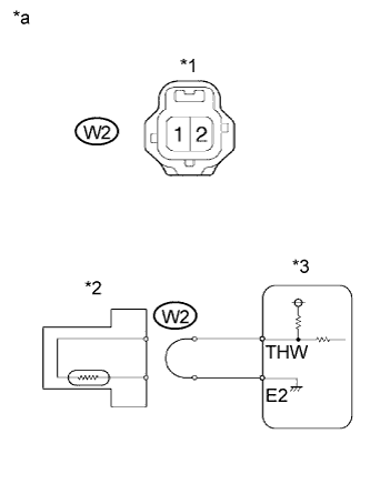
Text in Illustration *1 ECT Sensor Connector *2 ECT Sensor *3 ECM *a Wire Harness Side Disconnect the W2 Engine Coolant Temperature (ECT) sensor connector.
-
Connect terminals 1 and 2 of the ECT sensor connector on the wire harness side.
-
Connect an intelligent tester to the DLC3.
-
Turn the ignition switch ON and turn the tester ON.
-
Select the following menu items: Powertrain / Engine and ECT / Data List / Coolant Temp.
-
Read the value displayed on the tester.
Standard 140°C (284°F) or higher. -
Reconnect the ECT sensor connector.
OK
CONFIRM GOOD CONNECTION TO SENSOR. IF OK, REPLACE ENGINE COOLANT TEMPERATURE SENSOR
NG
-
-
READ VALUE USING INTELLIGENT TESTER (CHECK FOR OPEN IN ECM)
-
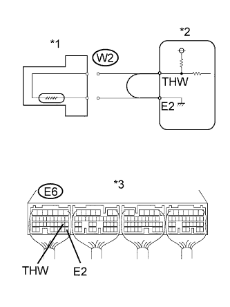
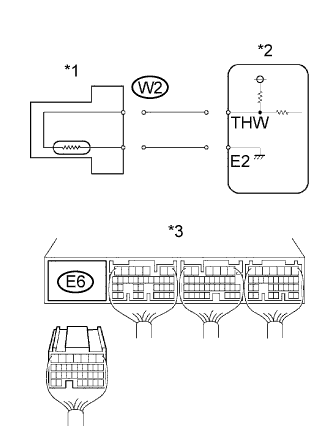
Text in Illustration *1 ECT Sensor *2 ECM *3 ECM Connector Disconnect the W2 ECT sensor connector.
-
Connect terminals THW and E2 of the E6 ECM connector.
Tech Tips
Before checking, perform a visual and contact pressure check on the ECM connector.
-
Connect an intelligent tester to the DLC3.
-
Turn the ignition switch ON and turn the tester ON.
-
Select the following menu items: Powertrain / Engine and ECT / Data List / Coolant Temp.
-
Read the value displayed on the tester.
Standard 140°C (284°F) or higher. -
Reconnect the ECT sensor connector.
OK
REPAIR OR REPLACE HARNESS OR CONNECTOR
NG 
CONFIRM GOOD CONNECTION TO ECM. IF OK, REPLACE ECM
-
-
READ VALUE USING INTELLIGENT TESTER (CHECK FOR SHORT IN WIRE HARNESS)
-
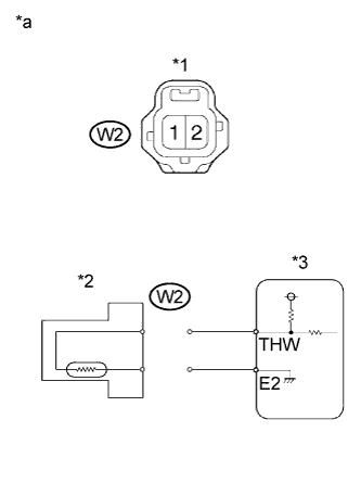
Text in Illustration *1 ECT Sensor Connector *2 ECT Sensor *3 ECM *a Wire Harness Side Disconnect the W2 ECT sensor connector.
-
Connect an intelligent tester to the DLC3.
-
Turn the ignition switch ON and turn the tester ON.
-
Select the following menu items: Powertrain / Engine and ECT / Data List / Coolant Temp.
-
Read the value displayed on the tester.
Standard -40°C (-40°F) -
Reconnect the ECT sensor connector.
OK
CONFIRM GOOD CONNECTION TO SENSOR. IF OK, REPLACE ENGINE COOLANT TEMPERATURE SENSOR
NG
-
-
READ VALUE USING INTELLIGENT TESTER (CHECK FOR SHORT IN ECM)
-
Text in Illustration *1 ECT Sensor Connector *2 ECT Sensor *3 ECM Disconnect the W2 ECT sensor connector.
-
Disconnect the E6 ECM connector.
-
Connect an intelligent tester to the DLC3.
-
Turn the ignition switch ON and turn the tester ON.
-
Select the following menu items: Powertrain / Engine and ECT / Data List / Coolant Temp.
-
Read the value displayed on the tester.
Standard -40°C (-40°F) -
Reconnect the ECT sensor connector.
-
Reconnect the ECM connector.
OK
REPAIR OR REPLACE HARNESS OR CONNECTOR
NG
REPLACE ECM
-