ECD SYSTEM (w/o EGR Cooler Bypass Valve) DATA LIST / ACTIVE TEST
-
READ DATA LIST
Tech Tips
Using the intelligent tester's Data List allows switch, sensor, actuator, and other item values to be read without removing any parts. Reading the Data List early in troubleshooting is one way to save time.
Note
In the table below, the values listed under "Normal Condition" are reference values. Do not depend solely on these reference values when deciding whether a part is faulty or not.
-
Warm up the engine.
-
Turn the ignition switch OFF.
-
Connect the intelligent tester to the DLC3.
-
Turn the ignition switch ON.
-
Turn the intelligent tester ON.
-
Select the following menu items: Powertrain / Engine and ECT / Data List.
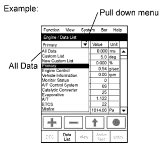
Tech Tips
To display the entire Data List, press the pull down menu button next to Primary. Then select All Data.
-
Read the Data List.
Tester Display Measurement Item/Range Normal Condition*
Diagnostic Note Calculate Load Calculated load by ECM/
Min.: 0%, Max.: 100%
-
11.4 to 16.4%: Idling
-
13.1 to 18.9%: Running without load (2,500 rpm)
- MAF Air flow rate from MAF meter status/
Min.: 0 gm/s, Max.: 655.35 gm/s
-
5 to 12 g/sec.: Idling
-
28 to 46 g/sec.: Running without load (2,000 rpm)
If value approximately 0 g/sec.:
-
Mass air flow meter power source circuit open
-
VG circuit open or shorted
If value 135 g/sec. or more:
-
E2G circuit open
MAP Absolute pressure inside intake manifold/
Min.: 0 kPa, Max.: 255 kPa
-
95 to 105 kPa: Idling
-
110 to 135 kPa:
Engine running at 3,000 rpm
-
Min.: 175 kPa:
Engine running at 3,500 rpm
- Engine Speed Engine speed/
Min.: 0 rpm, Max.: 16,383.75 rpm
700 to 800 rpm: Idling - Coolant Temp Engine coolant temperature/
Min.: -40°C, Max.: 140°C
75 to 90°C (167 to 194°F):
After warming up engine
If value is -40°C (-40°F) or 140°C (284°F), sensor circuit open or shorted Intake Air Intake air temperature/
Min.: -40°C, Max.: 140°C
Equivalent to temperature at intake manifold If value is -40°C (-40°F) or 140°C (284°F), sensor circuit open or shorted Vehicle Speed Vehicle speed/
Min.: 0 km/h, Max.: 255 km/h
Actual vehicle speed Speed indicated on speedometer Fuel Press Fuel pressure/
Min.: 0 MPa, Max.: 655.350 MPa
30 to 40 MPa: Idling - EGR Position EGR position/
Min: 0%, Max: 100%
Level surface, engine warmed up and idling: 0 to 65% - Accelerator Position No. 1 Accelerator position No. 1/
Min.: 0%, Max.: 100%
-
Accelerator pedal released:
8 to 28%
-
Accelerator pedal depressed:
51 to 71%
Read value with ignition switch ON (do not start engine) Accelerator Position No. 2 Accelerator position No. 2/
Min.: 0%, Max.: 100%
-
Accelerator pedal released:
30 to 55%
-
Accelerator pedal depressed:
73 to 98%
Read value with ignition switch ON (do not start engine) Fail Safe Drive Whether or not fail safe function executed:
ON or OFF
ON: ETCS (Electronic Throttle Control System) has failed - Fail Safe Drive (Main CPU) Whether or not fail safe function executed:
ON or OFF
ON: ETCS has failed - System Guard System guard:
ON or OFF
- ETCS service data Throttle Idle Position Throttle position sensor
detecting idle: ON or OFF
- - Throttle Motor Throttle motor status:
ON or OFF
ON: Idling - Initial Engine Coolant Temp Engine coolant temperature when engine starts:
Min.: -40°C, Max.: 120°C
Engine coolant temperature when engine starts - Initial Intake Air Temp Intake air temperature when engine starts:
Min.: -40°C, Max.: 120°C
Intake air temperature when engine starts - Intake Air Temp (Turbo) Intake air temperature passed through turbocharger:
Min.: -40°C, Max.: 190°C
- - EGR Lift Position Electric EGR control valve lift position:
Min.: 0 %, Max.: 100%
0 to 65%: Idling - EGR Close Learning Value Electric EGR control valve fully closed position learning value:
Min.: 0 V, Max.: 5V
0.15 to 1.45 V - Throttle Valve Fully Closed Throttle valve fully closed angle:
Min.: 0 deg, Max.: 84 deg
11 to 21 deg - Target Common Rail Pressure Target common rail pressure/
Min.: 0 kPa, Max.: 655,350 kPa
30,000 to 160,000 kPa - VNT Type VN turbo type:
Not Avl / Commo / Vacuum
Commo - VNT Max Angle VN turbo nozzle vane maximum opening angle:
Min.: 0 %, Max.: 100%
90%: Idling - VNT Min Angle VN turbo nozzle vane minimum opening angle:
Min.: 0 %, Max.: 100%
10 to 20%: Full - Injection Pressure Correction Injection pressure feedback correction:
Min.: -500 mm3/st
Max.: 780 mm3/st
-400 to 400 mm3/st
- EGR Valve Learning Value Electric EGR control valve lift learning value:
Min.: 0 V, Max.: 5 V
0 to 1.0 V: Idling - Alternate Duty Ratio Alternate duty ratio:
Min.: 0 %, Max.: 100 %
-
No electrical load:
20 to 60 %
-
High electrical load:
100 %
- Accel Position 1 Accelerator pedal position sensor No. 1 voltage/:
Min.: 0 V, Max.: 5 V
-
Accelerator pedal released:
0.5 to 1.1 V
-
Accelerator pedal depressed:
2.6 to 4.5 V
Read value with ignition switch ON (do not start engine) Accel Position 2 Accelerator pedal position sensor No. 2 voltage:
Min.: 0 V, Max.: 5 V
-
Accelerator pedal released:
1.2 to 2.0 V
-
Accelerator pedal depressed:
3.4 to 5.0 V
Read value with ignition switch ON (do not start engine) Accel Position Accelerator position status:
Min.: 0%, Max.: 100%
-
Accelerator pedal released:
0%
-
Accelerator pedal depressed:
100%
Read value with ignition switch ON (do not start engine) Fuel Temperature Fuel temperature/
Min.: -40°C, Max.: 140°C
Actual fuel temperature at supply pump ECD freeze frame data Diesel Throttle Angle Diesel throttle valve opening angle:
Min.: -20 %, Max.: 120 %
Idling after engine warmed-up: 79 to 93% ECD freeze frame data VNT Command VN turbo command:
Min.: 0%, Max.: 100%
0 to 100% ECD freeze frame data Pump VCM Angle Corrected current value flow to supply pump:
Min.: 0 mA, Max.: 4,000 mA
1,000 to 1,200 mA ECD freeze frame data IDL Stable Control IDL stable control (calculated value):
Min.: -80 mm3/st, Max.: 79 mm3/st
-10 to 10 mm3/st
ECD freeze frame data Common Rail Pres Sens 2 Common rail pressure senor (Sub):
Min.: 0 kPa, Max.: 655,350 kPa
30,000 to 40,000 kPa: Idling - Pilot 1 Injection No.1 pilot injection period:
Min.: 0 μs, Max.: 65,535 μs
380 to 480 μs: Idling - Pilot 2 Injection No.2 pilot injection period:
Min.: 0 μs, Max.: 65,535 μs
380 to 480 μs: Idling - Main Injection Main injection period:
Min.: 0 μs, Max.: 65,535 μs
510 to 710 μs: Idling - After Injection Main injection period:
Min.: 0 μs, Max.: 65,535 μs
- - Pilot 1 Injection No.1 pilot injection period:
Min.: -70°CA, Max.: 20°CA
-22 to -18°CA: idle after engine warmed up and vehicle is under normal atmospheric pressure - Pilot 2 Injection No.2 pilot injection period:
Min.: -50°CA, Max.: 20°CA
-16 to -11°CA: idle after engine warmed up and vehicle is under normal atmospheric pressure - Main Injection Main injection period:
Min.: -90°CA, Max.: 90°CA
0.5 to 4°CA: idle after engine warmed up and vehicle is under normal atmospheric pressure - After Injection After injection period:
Min.: -10°CA, Max.: 50°CA
- - Injection Feedback Value Injection volume feedback learning value:
Min.: -10 mm3/st, Max.: 9.92 mm3/st
-3.0 to 3.0 mm3/st: Idling
- Injection Feedback Val #1 Injection volume correction for cylinder 1:
Min.: -10 mm3/st, Max.: 10 mm3/st
-3.0 to 3.0 mm3/st: Idling
- Injection Feedback Val #2 Injection volume correction for cylinder 2:
Min.: -10 mm3/st, Max.: 10 mm3/st
-3.0 to 3.0 mm3/st: Idling
- Injection Feedback Val #3 Injection volume correction for cylinder 3:
Min.: -10 mm3/st, Max.: 10 mm3/st
-3.0 to 3.0 mm3/st: Idling
- Injection Feedback Val #4 Injection volume correction for cylinder 4:
Min.: -10 mm3/st, Max.: 10 mm3/st
-3.0 to 3.0 mm3/st: Idling
- Injection Volume Injection volume:
Min.: 0 mm3st, Max.: 1,279.98 mm3st
5 to 12 mm3st: Idling
- Diesel Throttle Learn Status Diesel throttle learning status:
OK or NG
OK - EGR Learning Status EGR learning status:
OK or NG
OK - Starter Signal Starter signal:
ON or OFF
ON: Cranking - A/C Signal A/C signal/
ON or OFF
ON: A/C ON - Stop Light Switch Stop light switch/:
ON or OFF
-
ON: Brake pedal depressed
-
OFF: Brake pedal released
- Battery Voltage Battery voltage:
Min.: 0 V
Max.: 65.535 V
9 to 14 V: Idling - Actuator Power Supply Actuator power supply:
ON or OFF
ON: Idling - Atmosphere Pressure Atmospheric pressure value:
Min.: 0 kPa (0 mmHg, 0 in.Hg),
Max.: 255 kPa (1,912.6 mmHg, 75.3 in.Hg)
Actual atmospheric pressure - Swirl Control Valve VSV VSV for Swirl control valve status:
ON or OFF
ON: Idling - EGR EGR status for Active Test:
ON or OFF
- Active Test support data TC and TE1 TC and TE1 terminal of DLC3 connection status for Active Test:
ON or OFF
- Active Test support date #Code #Code:
Min.: 0, Max.: 255
- Number of detected DTCs Check Mode Check mode:
ON or OFF
ON: Check mode ON - SPD Test Check mode result for vehicle speed sensor:
Compl or Incompl
- MIL MIL status:
ON or OFF
ON: MIL ON - MIL ON Run Distance MIL ON run distance:
Min.: 0 km
Max.: 65,535 km
Distance after DTC detected - Running Time from MIL ON Running time from MIL ON:
Min.: 0 minute
Max.: 65,535 minutes
Equivalent running time after MIL was ON - Distance from DTC Cleared Distance after DTC cleared:
Min.: 0 km
Max.: 65,535 km
Equivalent to drive distance after DTCs were erased - Warmup Cycle Cleared DTC Warmup cycle after DTC cleared:
Min.: 0
Max.: 255
- Number of warmup cycles after DTC cleared Engine Run Time Engine run time:
Min.: 0 second
Max.: 65,535 seconds
Time after engine started Service data Time After DTC Cleared Time after DTC cleared:
Min.: 0 minute
Max.: 65,535 minutes
Equivalent to time after DTCs were erased - OBD Requirements OBD application - Identifying applied OBD:
E-OBD
Number of Emission DTC Number of emission DTCs - - Complete Parts Monitor Complete parts monitor:
Not Avl or Avail
- - Fuel System Monitor Fuel system monitor:
NOT AVL or AVAIL
- - EGR Monitor EGR monitor:
Not Avl or Avail
- - EGR Monitor EGR monitor:
Compl or Incmpl
- - Model Code Identifying model code - Identifying model code:
KDY2#
Engine Type Identifying engine type - Identifying engine type/
1KDFTV
Transmission (Engine) Type Identifying transmission type Identifying transmission type:
MT
Cylinder Number Cylinder number:
Min.: 0, Max.: 255
- Identifying cylinder number/
4
Destination Identifying destination - Identifying destination/
W
Model Year Model year/
Min.: 1900 MY, Max.: 2155 MY
- Identifying destination/
200#
System Identification Identifying engine system - Identifying engine type:
Diesel (diesel engine)
Tech Tips
*: If no idling conditions are specified, the shift lever is in the N position, and the A/C switch and all accessory switches are OFF.
-
-
-
PERFORM ACTIVE TEST
Tech Tips
Performing the intelligent tester's Active Test allows relay, VSV, actuator and other items to be operated without removing any parts. Performing the Active Test early in troubleshooting is one way to save time.
The Data List can be displayed during the Active Test.
-
Connect the intelligent tester to the DLC3.
-
Turn the ignition switch ON.
-
Turn the intelligent tester ON.
-
Select the following menu items: Powertrain / Engine and ECT / Active Test.
-
Perform the Active Test.
Tester Display Test Part Control Range Diagnostic Note Activate the VSV for Swirl Control Valve VSV for swirl control valve ON/OFF - Control the EGR System Activate E-VRV for EGR ON/OFF - Activate the VSV for EGR Cut Activate VSV for EGR Cut ON/OFF - Control the A/C cut Signal Control the A/C signal ON/OFF - Connect the TC and TE1 Turn on TC and TE1 connection ON/OFF - Control the Cylinder#1 Fuel Cut Cut off fuel injection from No. 1 injector ON/OFF Fuel injection stopped while test is ON Control the Cylinder#2 Fuel Cut Cut off fuel injection from No. 2 injector ON/OFF As above Control the Cylinder#3 Fuel Cut Cut off fuel injection from No. 3 injector ON/OFF As above Control the Cylinder#4 Fuel Cut Cut off fuel injection from No. 4 injector ON/OFF As above Test the Turbo Charger Step Motor Activate DC motor for turbocharger 40 to 100 % Active test available only while engine idling or not running (ignition switch ON) Test the Fuel Leak Pressurizes common rail internal fuel pressure, and checks for fuel leaks Stop/Start
-
Fuel pressure inside common rail pressurized to specified value and engine speed increased to 2,000 rpm when ON is selected
-
Above conditions preserved while test is ON
-
-