ECD SYSTEM (w/o EGR Cooler Bypass Valve) Black Smoke Emitted
DESCRIPTION
-
Faults and Symptoms of Common Rail Diesel Components
-
Engine Control
Intake System Symptom and Corresponding Main Fault
-
Lack of power (no black smoke) due to air filter blockage or crushed or leaking air duct
-
Black smoke (no lack of power) due to leakage between the turbo and intake manifold
Data List MAP Glow System Main fault Glow system malfunction Symptoms Difficult to start, rough idle, knocking, white smoke (when cold) Data List Check the glow plug indicator light Diagnostic Point Measure the resistance of the glow plug Engine Main fault Loss of compression Symptoms Rough idle (lack of power always) Data List Injection Feedback Val
-
When an Injector Feedback Val is more than 3 mm3/st, there may be a malfunction in the corresponding cylinder.
-
-
Diesel Injection
Fuel Supply Pump Main fault - Symptoms Difficult to start, engine stalling, rough idle, lack of power Data List Fuel Press, Target Common Rail Pressure
-
Fuel Press is within 5000 kPa of Target Common Rail Pressure during idling with the engine warmed up (engine coolant temperature is higher than 70°C (158°F)).
-
If the fuel pressure is 20000 kPa below the target pressure, then a lack of power will be felt.
-
If the fuel pressure is below 25000 kPa, then idling will be rough.
Tech Tips
The fuel pressure changes at engine start, but is approx. 25000 kPa at engine start after the engine is warmed up.
Diagnostic Trouble Code Even if Fuel Press is below Target Common Rail Pressure, a DTC will not be stored. Injector Assembly Main fault Blockage, increase in fuel injection volume Symptoms Rough idle, lack of power, black smoke, white smoke, knocking Data List Injection Feedback Val
-
When an Injector Feedback Val is more than 3 mm3/st, there may be a malfunction in the corresponding cylinder. This value can be read after idling for 1 minute.
Tech Tips
-
When the sliding resistance of the internal parts of the injector assemblies (i.e. armature shaft, command piston and plunger) has increased due to internal contamination, injection quantity will increase at high common rail pressure due to a delay in injector assembly closure.
-
When black smoke occurs due to contamination of the injector assemblies, there are usually other symptoms, such as engine knocking noise at cold idling, rough idling, difficulty starting, etc. which are also present when the common rail pressure is low.
Injector Driver Main fault Circuit fault: The injector assembly does not open. Symptoms Difficult to start, rough idle, lack of power, black smoke, white smoke, knocking Data List Same as injector assembly Diagnostic Trouble Code When the injector driver has a fault, some DTCs may be stored. Fuel Pressure Sensor Main fault Open circuit, decrease in performance (foreign matter is stuck) Symptoms Difficult to start, rough idle, engine stall, lack of power Data List Fuel Press, Target Common Rail Pressure
-
Slowly raise the engine speed from idling to 3000 rpm with the vehicle stopped and check that Fuel Press and Common Rail Pres Sens 2 follow Target Common Rail Pressure. If the fuel pressure sensor malfunctions, the actual fuel pressure may deviate from the target fuel pressure (either Fuel Press or Common Rail Pres Sens 2 decreases to a value less than Target Common Rail Pressure).
Diagnostic Trouble Code When the fuel pressure sensor has a fault, some DTCs may be stored. Irregular Fuel Main fault - Symptoms Difficult to start, rough idle (especially when cold) -
-
Diesel EGR
EGR System Main fault
-
Does not move smoothly
-
Does not close completely
Symptoms
-
Rough idle
-
EGR valve stuck closed: A loud turbocharger sound.
-
EGR valve stuck open: Difficult to start (does not stall), black smoke, lack of power (if there is an excess in the quantity of EGR and there is a heavy load, when the vehicle starts moving, a lack of power will be felt).
-
-
Diesel Throttle
Diesel Throttle System Main fault Stuck, does not move smoothly Symptoms
-
Stuck closed: Lack of power, difficult to start, rough idle, engine stall, black smoke. These may occur when stuck almost fully closed.
-
Stuck open: Turbocharger sound increases. When the engine is stopped, engine vibrations may occur.
-
-
-
Data List Related to Black Smoke
-
Engine Speed
-
MAP
-
MAF
-
Intake Air
-
Coolant Temp
-
Target Common Rail Pressure
-
Fuel Press
-
Injection Feedback Val #1 (to #4)
-
Injection Volume
-
INSPECTION PROCEDURE
Note
-
After replacing the ECM, the new ECM needs registration Click here and initialization Click here.
-
After replacing a Fuel Supply Pump, the ECM needs initialization Click here.
-
After replacing an injector assembly, the ECM needs registration Click here.
Tech Tips
Specified values in the following troubleshooting flowchart are for reference only. Variations in the Data List values may occur depending on the measuring conditions or the vehicle age. Do not assume the vehicle to be normal when the Data List outputs standard values. There may be concealed factors of the malfunction.
-
Explanation of Symptom
Black Smoke The fuel used in diesel engines has a higher boiling point and evaporates much slower than that used in gasoline engines. Additionally, the fuel is injected directly, so the air fuel mixture in diesel engines is formed in a very short period of time and is less homogenous. This is why diesel engines must operate with a larger air fuel ratio across the entire operating range. An insufficient quantity of air results in imperfect combustion and increased particulate (soot) emissions.
When the accelerator pedal is depressed, a large amount of fuel is injected. As a result, the air fuel ratio becomes rich. In this relatively rich environment, fuel droplets lacking in oxygen burn imperfectly producing soot, which is emitted as black smoke. In order to prevent black smoke production, the maximum injection quantity for a given intake air mass is limited (final injection quantity is limited by MAF).
Black smoke is emitted when either 1) a lack of oxygen is present during combustion, or 2) Too much fuel is injected for a given intake air mass and the air fuel ratio becomes temporarily rich.
PROCEDURE
-
READ OUTPUT DTC (RELATING TO ENGINE)
-
Connect the intelligent tester to the DLC3.
-
Turn the ignition switch to ON and turn the tester on.
-
Enter the following menus: Powertrain / Engine and ECT / DTC.
-
Read the pending DTCs.
Result Result Proceed to No DTCs are output A Engine related DTCs are output B
B 
GO TO DTC CHART Click here
A 
-
-
CHECK FOR BLACK SMOKE
-
Start the engine and drive the vehicle until the engine coolant temperature reaches 60°C (140°F) or higher.
-
Stop the vehicle and allow the engine to idle.
-
Fully depress the accelerator pedal for 5 seconds, and then release it.*1
-
Repeat the above procedure *1 10 times or more.*2
-
Check for black smoke emission during procedures *1 and *2.
OK Black smoke is emitted less than 5 times. Tech Tips
-
Even if the black smoke is very thin, count the number of black smoke emissions if there is any visible smoke.
-
If the procedure is repeated 10 times or more and black smoke stops being emitted, this probably means that the black smoke was caused by a temporary accumulation of soot which occurred when driving at low speeds, and is not a malfunction.
-
OK 
RECOVERY TO NORMAL Click here
NG
CHECK AIR INTAKE SYSTEM Click here
-
-
CHECK AIR INTAKE SYSTEM
-
Check for air leakage and blockage between the air cleaner and turbocharger, and between the turbocharger and intake manifold.
Tech Tips
-
Make sure that the air cleaner is not clogged and the intake and exhaust system hoses are not disconnected.
-
When the vacuum hoses are disconnected (the swirl control valve is always fully open) or the valve is stuck open, smoke may increase without feeling a lack of power (visually check the operation of the swirl control valve when starting the engine).
-
Check that the intercooler is not clogged with foreign matter.
-
Check that there are no disconnected, pinched or leaking hoses or pipes.
-
Check that there are no modifications made by the user.
OK No leakage or blockage. -
NG
REPAIR OR REPLACE MALFUNCTIONING PARTS
OK
-
-
CHECK WIRE HARNESS AND CONNECTION IN ENGINE COMPARTMENT
-
Check the wire harness and connector connections of common rail system components.
OK The wire harnesses and connectors are connected securely.
NG
REPAIR OR REPLACE HARNESS OR CONNECTOR Click here
OK
-
-
CHECK INJECTOR COMPENSATION CODE
-
Read the injector compensation codes Click here.
OK Compensation codes stored in the ECM match the compensation codes of the installed injector assemblies.
NG
PERFORM ECM INITIALIZATION AND REGISTER INJECTOR COMPENSATION CODE Click here
OK
-
-
TAKE SNAPSHOT DURING IDLING AND 4000 RPM (AFTER ENGINE WARMED UP)
-
Connect the intelligent tester to the DLC3.
-
Start the engine and turn the tester on.
-
Enter the following menus: Powertrain / Engine and ECT / Data List / All Data.
-
Take a snapshot of the following Data List items.
Tech Tips
-
A snapshot can be used to compare vehicle data from the time of the malfunction to normal data and is very useful for troubleshooting. The data in the list below is that of a normal vehicle, but as the data varies between individual vehicles, this data should only be used for reference.
-
Graphs like the ones shown below can be displayed by transferring the stored snapshot data from the tester to a PC. Intelligent Viewer must be installed on the PC.
-
Check the Data List at idling and at 4000 rpm with no load after the engine is warmed up.
-
NEXT
-
-
READ VALUE USING INTELLIGENT TESTER (MAF AND MAP)
-
Connect the intelligent tester to the DLC3.
-
Start the engine and turn the tester on.
-
Warm up the engine (engine coolant temperature is 70°C (158°F) or higher).
-
Enter the following menus: Powertrain / Engine and ECT / Data List / MAP and MAF.
-
Take a snapshot when the engine speed is maintained at 4000 rpm with no load.
-
Read the values of "MAP" and "MAF" in the Data List using the snapshot review function.
Result Result Proceed to MAF 104 gm/s or more and MAP 114 kPa or higher A Except above B Tech Tips
-
The shift lever should be in neutral and the A/C switch and all accessory switches should be off.
-
The above values were measured under standard atmospheric pressure. The values are influenced by elevation, weather conditions, etc.
Standard atmospheric pressure is 101 kPa. For every 100 m increase in elevation, pressure drops by 1 kPa. This varies by weather.
-
A
CHECK SNAPSHOT (INJECTION VOLUME AND INJECTION FEEDBACK VAL #1 TO #4) Click here
B
-
-
PERFORM ACTIVE TEST USING INTELLIGENT TESTER (ACTIVATE THE VSV FOR EGR CUT)
-
Connect the intelligent tester to the DLC3.
-
Start the engine and warm it up, and make sure the A/C switch and all accessory switches are off.
-
Turn the ignition switch off. Wait for 30 seconds, and then restart the engine.
-
Turn the tester on.
-
Enter the following menus: Powertrain / Engine and ECT / Data List / MAF.
-
Read the MAF value displayed on the tester while the engine is idling.
-
Enter the following menus: Powertrain / Engine and ECT / Active Test / Activate The VSV for EGR Cut.
-
Read the MAF value when the EGR valve is closed using the Active Test function.
Tech Tips
-
If idling continues for 20 minutes or more, the EGR valve target opening angle becomes 0% (EGR valve fully closed). As this makes diagnosis impossible, it becomes necessary to drive the vehicle or restart the engine.
-
Before performing the diagnosis, confirm that the EGR valve target opening angle is not 0%.
Result Active Test Result Proceed to Activate The VSV for EGR Cut:
off (Open) to on (Close)
MAF value does not change A MAF value changes B Note
As the measured values may differ from those shown below due to factors such as differences in measuring environments and changes in vehicle condition due to aging, do not use these values to determine whether the vehicle is malfunctioning or not.
Tech Tips
The problem may be a temporary one, due to the entry of deposits or foreign matter. Check that there are no deposits or foreign matter in the electric vacuum regulating valve assembly or mass air flow meter.
Reference EGR Valve Condition (Opening) Measuring Condition MAF (Reference) Open (55%)
-
Atmosphere pressure: 101 kPa
-
Intake air temperature: 30°C (86°F)
-
Engine coolant temperature: 88°C (190°F)
7 to 13 gm/s Closed (0%) 15 to 22 gm/s -
B
CHECK SNAPSHOT (INJECTION VOLUME AND INJECTION FEEDBACK VAL #1 TO #4) Click here
A
-
-
READ VALUE USING INTELLIGENT TESTER (MAF)
-
Connect the intelligent tester to the DLC3.
-
Turn the ignition switch to ON and turn the tester on.
-
Enter the following menus: Powertrain / Engine and ECT / Data List / MAF.
-
With the ignition switch ON and engine stopped, read the value when 30 seconds has elapsed.
Standard Tester Display Switch Condition Standard MAF Ignition switch ON (do not start engine) Less than 0.5 gm/s
NG
REPLACE MASS AIR FLOW METER Click here
OK
-
-
REMOVE DEPOSIT (ELECTRIC EGR CONTROL VALVE ASSEMBLY)
-
Remove the electric EGR control valve assembly Click here.
-
Visually check the electric EGR control valve assembly for deposits. If there are deposits, clean the electric EGR control valve assembly.
Tech Tips
-
If the EGR valve does not open properly or is stuck closed, the amount of intake air increases and combustion sounds and engine vibration may increase.
-
If the EGR valve does not operate due to clogging or disconnection of the vacuum hose, repair the hose.
-
If the EGR valve does not close properly or is stuck open, EGR becomes excessive and combustion becomes unstable. Also, there may be a lack of power. In this case, clean the electric EGR control valve assembly.
-
When cleaning the electric vacuum regulating valve assembly, use a piece of cloth soaked with non-residue solvent. Spraying the solvent directly onto these parts or soaking the parts in solvent may damage the parts.
-
-
Reinstall the electric EGR control valve assembly Click here.
NEXT
CHECK FOR BLACK SMOKE Click here
-
-
REPLACE MASS AIR FLOW METER
-
Replace the mass air flow meter Click here.
NEXT
CHECK FOR BLACK SMOKE Click here
-
-
CHECK SNAPSHOT (INJECTION VOLUME AND INJECTION FEEDBACK VAL #1 TO #4)
-
Check Injection Feedback Val # and Injection Volume in the snapshot taken after the engine is warmed up and idled for 1 minute.
Result Result Proceed to Injection Volume is less than 9 mm3/st at 4000 rpm
A Injection Feedback Val for at least one cylinder is more than +3 mm3/st
B Except above C
B
CHECK CYLINDER COMPRESSION PRESSURE Click here
C
READ VALUE USING INTELLIGENT TESTER (MAP AND ATMOSPHERE PRESSURE) Click here
A
-
-
REPLACE INJECTOR ASSEMBLIES OF ALL CYLINDERS
-
Replace the injector assemblies Click here.
Note
-
When replacing the injector assembly for a cylinder, always be sure to use a new injection pipe.
-
Follow the procedure in the repair manual and temporarily install the injection pipes and nozzle leakage pipe, and then correctly position the injector assemblies. After that, tighten parts according to the torque specifications.
-
If the installation procedure is not performed correctly, injector assemblies may become out of position, which may cause the injector assemblies to deteriorate, resulting in malfunctions.
-
If an injector assembly deteriorates and malfunctions, other problems such as knocking, rough idle, etc. may occur.
-
If an injector assembly becomes out of position, it is possible that the seal between the injector assembly and injection pipe may become incomplete, resulting in a fuel leak.
-
NEXT
REPLACE FUEL FILTER ELEMENT SUB-ASSEMBLY Click here
-
-
CHECK CYLINDER COMPRESSION PRESSURE
-
Check the cylinder compression pressure Click here.
Tech Tips
When compression is low, there may be cracks in the piston or the injector may be installed improperly.
NG
CHECK ENGINE TO DETERMINE CAUSE OF LOW COMPRESSION
OK
-
-
REPLACE INJECTOR ASSEMBLY OF MALFUNCTIONING CYLINDER
-
Replace the injector assembly of the malfunctioning cylinder Click here.
Note
-
When replacing the injector assembly for a cylinder, always be sure to use a new injection pipe.
-
Follow the procedure in the repair manual and temporarily install the injection pipes and nozzle leakage pipe, and then correctly position the injector assemblies. After that, tighten parts according to the torque specifications.
-
If the installation procedure is not performed correctly, injector assemblies may become out of position, which may cause the injector assemblies to deteriorate, resulting in malfunctions.
-
If an injector assembly deteriorates and malfunctions, other problems such as knocking, rough idle, etc. may occur.
-
If an injector assembly becomes out of position, it is possible that the seal between the injector assembly and injection pipe may become incomplete, resulting in a fuel leak.
-
NEXT
-
-
REPLACE FUEL FILTER ELEMENT SUB-ASSEMBLY
-
Replace the fuel filter element sub-assembly Click here.
NEXT
-
-
BLEED AIR FROM FUEL SYSTEM
-
Bleed the air from the fuel system Click here.
NEXT
-
-
PERFORM ECM INITIALIZATION AND REGISTER INJECTOR COMPENSATION CODE
-
Perform the ECM initialization.
-
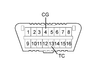
Connect terminals 13 (TC) and 4 (CG) of the DLC3.
-
Turn the ignition switch to ON for 50 minutes or more.
Note
-
Perform ECM initialization only when the injectors for all the cylinders have been replaced.
-
It is necessary to wait for 50 minutes or more. Otherwise, ECM initialization is not completed.
-
-
Turn the ignition switch off.
-
Disconnect terminals 13 (TC) and 4 (CG).
-
-
Register the injector compensation code Click here.
NEXT
-
-
CHECK FOR BLACK SMOKE
-
Start the engine and drive the vehicle until the engine coolant temperature reaches 60°C (140°F) or higher.
-
Stop the vehicle and allow the engine to idle.
-
Fully depress the accelerator pedal for 5 seconds, and then release it.*1
-
Repeat the above procedure *1 10 times.*2
-
Check for black smoke emission during procedures *1 and *2.
OK Black smoke is emitted less than 5 times. Tech Tips
Even if the black smoke is very thin, count the number of black smoke emissions if there is any visible smoke.
NEXT 
END
-
-
READ VALUE USING INTELLIGENT TESTER (MAP AND ATMOSPHERE PRESSURE)
-
Connect the intelligent tester to the DLC3.
-
Turn the ignition switch to ON and turn the tester on.
-
Enter the following menus: Powertrain / Engine and ECT / Data List / MAP and Atmosphere Pressure.
-
Compare MAP to Atmosphere Pressure when the ignition switch to ON (engine stopped).
Tech Tips
-
If MAP and Atmosphere Pressure have the same value, both are normal. If there is a difference of 10 kPa (0.1 kgf/cm2, 1.5 psi) or more, compare the values to the atmospheric pressure for that day. The sensor whose deviation is the greatest is malfunctioning.
-
Standard atmospheric pressure is 101 kPa (1.0 kgf/cm2, 15 psi). For every 100 m (328 ft.) increase in elevation, pressure drops by 1 kPa (0.01 kgf/cm2, 0.1 psi). This varies by weather (high atmospheric pressure, low atmospheric pressure).
Result Result Proceed to MAP and Atmosphere Pressure have same value A Atmosphere Pressure is different from actual atmospheric pressure B MAP is different from actual atmospheric pressure C -
B
REPLACE ECM Click here
C
REPLACE MANIFOLD ABSOLUTE PRESSURE SENSOR Click here
A
-
-
PERFORM ACTIVE TEST USING INTELLIGENT TESTER (TEST THE FUEL LEAK)
-
Connect the intelligent tester to the DLC3.
-
Start the engine and turn the tester on.
-
Enter the following menus: Powertrain / Engine and ECT / Active Test / Test the Fuel Leak / Data List / Fuel Press, Target Common Rail Pressure.
-
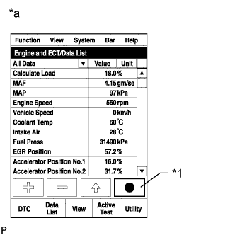
Text in Illustration *1 Snapshot Button *a Reference Take a snapshot with the intelligent tester during the Active Test.
Tech Tips
Detailed graphs can be displayed by transferring the stored snapshot from the tester to a PC (Personal Computer) with Intelligent Viewer installed.
-
Measure the difference between the target fuel pressure (Target Common Rail Pressure) and the actual fuel pressure (Fuel Press) when the "Test the Fuel Leak" Active Test is performed.
Tech Tips
In order to obtain an exact measurement, perform the Active Test 5 times and measure the difference once each time the Active Test is performed.
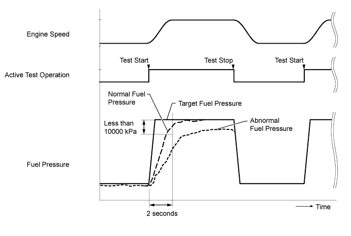
OK The difference between the target fuel pressure and the actual fuel pressure 2 seconds after the Active Test starts is less than 10000 kPa (102.0 kgf/cm2, 1451 psi). Tech Tips
-
"Target Common Rail Pressure" is the target fuel pressure controlled by the ECM.
-
"Fuel Press" is the actual fuel pressure in common rail assembly.
-
When the pressure discharge valve on the common rail assembly has a malfunction, the actual fuel pressure changes as shown by "Pressure Discharge Valve Abnormal Fuel Pressure" in the illustration.
-
The pressure discharge valve operates to discharge fuel pressure when the internal pressure of the common rail exceeds the target fuel pressure.
-
There are 2 fuel pressure sensor circuits and both of them display the same value. If the difference between Fuel Press and Common Rail Press Sens 2 exceeds 10000 kPa (102 kgf/cm2, 1451 psi) for 2 seconds or more, it is necessary to inspect or repair the wiring for the fuel pressure sensor.
-
NG
CHECK IF FUEL IS BEING SUPPLIED TO FUEL SUPPLY PUMP Click here
OK
-
-
READ VALUE USING INTELLIGENT TESTER (ENGINE COOLANT TEMPERATURE)
-
Connect the intelligent tester to the DLC3.
-
Soak the engine for a long time.
-
Turn the ignition switch to ON and turn the tester on.
-
Enter the following menus: Powertrain / Engine and ECT / Data List / Coolant Temp.
OK Coolant Temp is the same as the ambient temperature. Tech Tips
When the engine coolant temperature is low even though the engine has been fully warmed up, or when the engine coolant temperature is high even though the engine is cold, inspect the sensor.
NG
CHECK AND REPLACE ENGINE COOLANT TEMPERATURE SENSOR Click here
OK
-
-
READ VALUE USING INTELLIGENT TESTER (INTAKE AIR AND INTAKE AIR TEMP (TURBO))
-
Connect the intelligent tester to the DLC3.
-
Soak the engine for a long time.
-
Turn the ignition switch to ON and turn the tester on.
-
Enter the following menus: Powertrain / Engine and ECT / Data List / Intake Air, Intake Air Temp (Turbo).
OK Intake Air is the same as Intake Air Temp (Turbo).
OK
CHECK FOR BLACK SMOKE Click here
NG
CHECK AND REPLACE MALFUNCTIONING PARTS Click here
-
-
CHECK IF FUEL IS BEING SUPPLIED TO FUEL SUPPLY PUMP
-
Disconnect the inlet hose from the Fuel Supply Pump.
-
Operate the priming pump and check that fuel is being supplied to the Fuel Supply Pump.
OK Fuel is properly supplied to the Fuel Supply Pump when the priming pump is operated. Tech Tips
-
When there is a lack of fuel, the fuel pressure drops.
-
If "Fuel pressure" follows "Target common rail pressure" during idling or low speed driving but is insufficient during acceleration or high speed driving, the fuel filter may be clogged.
-
Inspect for fuel filter clogging (Check that the fuel filter is not clogged).
-
-
Reconnect the inlet hose.
NG
CHECK AND REPLACE CLOGGED FUEL PIPE (INCLUDING FROZEN FUEL) (FUEL TANK - FUEL SUPPLY PUMP) Click here
OK
-
-
REPLACE SUCTION CONTROL VALVE
-
Replace the suction control valve Click here.
NEXT
-
-
BLEED AIR FROM FUEL SYSTEM
-
Bleed the air from the fuel system Click here.
NEXT
-
-
PERFORM FUEL SUPPLY PUMP INITIALIZATION
-
Perform supply pump initialization Click here.
NEXT
CHECK FOR BLACK SMOKE Click here
-
-
REPLACE ECM
-
Replace the ECM Click here.
NEXT
CHECK FOR BLACK SMOKE Click here
-
-
REPLACE MANIFOLD ABSOLUTE PRESSURE SENSOR
-
Replace the manifold absolute pressure sensor.
NEXT
CHECK FOR BLACK SMOKE Click here
-
-
CHECK AND REPLACE ENGINE COOLANT TEMPERATURE SENSOR
-
Inspect the engine coolant temperature sensor Click here.
-
Replace the engine coolant temperature sensor Click here.
Tech Tips
It is only necessary to replace the part when the results of the inspection indicate a problem.
NEXT
CHECK FOR BLACK SMOKE Click here
-
-
CHECK AND REPLACE MALFUNCTIONING PARTS
-
Inspect the mass air flow meter Click here.
-
Inspect the intake air temperature sensor (turbo) Click here.
-
Replace the mass air flow meter Click here.
Tech Tips
It is only necessary to replace the part when the results of the inspection indicate a problem.
-
Replace the intake air temperature sensor (turbo) Click here.
Tech Tips
It is only necessary to replace the part when the results of the inspection indicate a problem.
NEXT
CHECK FOR BLACK SMOKE Click here
-
-
REPAIR OR REPLACE HARNESS OR CONNECTOR
-
Repair or replace the harness or connector.
NEXT
CHECK FOR BLACK SMOKE Click here
-
-
CHECK AND REPLACE CLOGGED FUEL PIPE (INCLUDING FROZEN FUEL) (FUEL TANK - FUEL SUPPLY PUMP)
-
Check and replace the clogged fuel pipe.
NEXT
-
-
BLEED AIR FROM FUEL SYSTEM
-
Bleed the air from the fuel system Click here.
NEXT
-
-
CHECK FOR BLACK SMOKE
-
Start the engine and drive the vehicle until the engine coolant temperature reaches 60°C (140°F) or higher.
-
Stop the vehicle and allow the engine to idle.
-
Fully depress the accelerator pedal for 5 seconds, and then release it.*1
-
Repeat the above procedure *1 10 times.*2
-
Check for black smoke emission during procedures *1 and *2.
OK Black smoke is emitted less than 5 times. Tech Tips
Even if the black smoke is very thin, count the number of black smoke emissions if there is any visible smoke.
NEXT
END
-
-
RECOVERY TO NORMAL
Tech Tips
If the racing procedure is repeated 10 times or more and black smoke stops being emitted, this probably means that the black smoke was caused by a temporary accumulation of soot which occurred when driving at low speeds, and is not a malfunction.
NEXT
END