ECD SYSTEM (w/ EGR Cooler Bypass Valve) DATA LIST / ACTIVE TEST
-
DATA LIST
Tech Tips
Using the intelligent tester to read the Data List allows the values or states of switches, sensors, actuators and other items to be read without removing any parts. This non-intrusive inspection can be very useful because intermittent conditions or signals may be discovered before parts or wiring is disturbed. Reading the Data List information early in troubleshooting is one way to save diagnostic time.
Note
In the table below. the values listed under "Normal Condition" are reference values. Do not depend solely on these reference values when deciding whether a part is faulty or not.
-
Warm up the engine.
-
Turn the ignition switch off.
-
Connect the intelligent tester to the DLC3.
-
Turn the ignition switch to ON.
-
Start the engine.
-
Turn the tester on.
-
Select the following menus: Powertrain / Engine and ECT / Data List.
Tech Tips
-
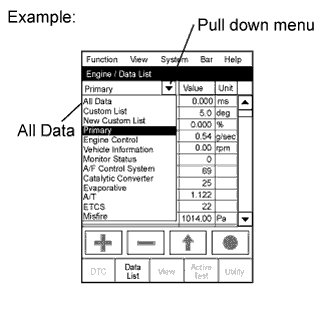
To display the list box, press the pull down menu button next to Primary. Then select a measurement group.
-
When you select a measurement group, the ECU data belonging to that group is displayed.
-
Measurement Group List / Description
-
All Data / All data
-
Primary / -
-
Engine Control / Engine control system related data
-
Vehicle Information / Vehicle information
-
Monitor Status / Monitor status related data
-
AF Control System / Not Applicable
-
Catalytic Converter / Not Applicable
-
Evaporative / Not Applicable
-
A/T / Automatic transmission system related data
-
ETCS / Not Applicable
-
Misfire / Not Applicable
-
Compression / Data used during "Check the Cylinder Compression "in Active Test"
-
HC Adsorber System / Not Applicable
-
Diesel Driving / Driving condition data
-
Diesel Injection / Fuel system related data
-
Diesel EGR / EGR system related data
-
Diesel Throttle / Diesel throttle system related data
-
Diesel VN Turbo / VN turbo related data
-
Diesel Exhaust / Exhaust system related data
-
Diesel Starting / "Difficult to start" related data
-
Diesel Rough / "Rough idle" related data
-
Diesel Power / "Lack of power" related data
-
-
Check the values by referring to the table below.
Engine Control Tester Display Measurement Item/Range Normal Condition*
Diagnostic Note Vehicle Speed Vehicle speed/
Min.: 0 km/h, Max.: 255 km/h
Actual vehicle speed Speed indicated on speedometer Engine Speed Engine speed/
Min.: 0 rpm, Max.: 16,383.75 rpm
700 to 800 rpm: Idling - Calculate Load Calculated load by ECM/
Min.: 0%, Max.: 100%
-
11.4 to 16.4%: Idling
-
13.1 to 18.9%: Running without load (2,500 rpm)
- MAF Air flow rate from MAF meter status/
Min.: 0 g/s, Max.: 655.35 g/s
-
3 to 9 g/sec.: Idling
-
30 to 50 g/sec.: Running without load (3,000 rpm)
If value approximately 0 g/sec.:
-
Mass air flow meter power source circuit open
-
VG circuit open or shorted
If value 135 g/sec. or more:
-
E2G circuit open
Atmosphere Pressure Atmospheric pressure value:
Min.: 0 kPa (0 mmHg, 0 in.Hg),
Max.: 255 kPa (1,912.6 mmHg, 75.3 in.Hg)
Actual atmospheric pressure - Coolant Temp Engine coolant temperature/
Min.: -40°C, Max.: 140°C
80 to 100°C (176 to 212°F):
After warming up engine
If value is -40°C (-40°F) or 140°C (284°F), sensor circuit open or shorted Intake Air Intake air temperature/
Min.: -40°C, Max.: 140°C
Equivalent to temperature at intake manifold If value is -40°C (-40°F) or 140°C (284°F), sensor circuit open or shorted Intake Air Temp (Turbo) Intake air temperature passed through turbocharger sub-assembly:
Min.: -40°C, Max.: 190°C
- - Engine Run Time Engine run time:
Min.: 0 second
Max.: 65,535 seconds
Time after engine started Service data Initial Engine Coolant Temp Engine coolant temperature when engine starts:
Min.: -40°C, Max.: 120°C
Engine coolant temperature when engine starts - Initial Intake Air Temp Intake air temperature when engine starts:
Min.: -40°C, Max.: 120°C
Intake air temperature when engine starts - Battery Voltage Battery voltage:
Min.: 0 V
Max.: 65.535 V
11 to 14 V: Idling - Alternate Duty Ratio Alternate duty ratio:
Min.: 0%, Max.: 100%
-
No electrical load:
20 to 60%
-
High electrical load:
100%
- Accel Position Accelerator position status:
Min.: 0%, Max.: 100%
-
Accelerator pedal released:
15 to17%
-
Accelerator pedal depressed:
60 to70%
Read value with ignition switch ON (do not start the engine) Accel Sens. No.1 Volt % Accelerator position No. 1/
Min.: 0%, Max.: 100%
-
Accelerator pedal released:
8 to 28%
-
Accelerator pedal depressed:
51 to 86%
Read value with ignition switch ON (do not start the engine) Accel Sens. No.2 Volt % Accelerator position No. 2/
Min.: 0%, Max.: 100%
-
Accelerator pedal released:
30 to 55%
-
Accelerator pedal depressed:
73 to 98%
Read value with ignition switch ON (do not start the engine) Starter Signal Starter signal:
on or off
on: Cranking - Clutch Switch Clutch switch:
on or off
on: Clutch pedal depressed - Stop Light Switch Stop light switch assembly/:
on or off
-
on: Brake pedal depressed
-
off: Brake pedal released
- A/C Signal A/C signal/
on or off
on: A/C on - Check Mode Check mode:
on or off
on: Check mode on - SPD Test Result Check mode result for vehicle speed sensor:
Compl or Incompl
- Complete Parts Monitor Complete parts monitor:
Not Avl or Avail
- - Fuel System Monitor Fuel system monitor:
NOT Avl or Avail
- - Misfire Monitor Misfire monitor:
NOT Avl or Avail
- - EGR/VVT Monitor EGR monitor:
Not Avl or Avail
- - EGR/VVT Monitor EGR monitor:
Compl or Incmpl
- - O2S(A/FS) Heater Monitor O2S (A/FS) heater monitor:
Not Avl or Avail
- - O2S(A/FS) Heater Monitor O2S (A/FS) heater monitor:
Compl or Incmpl
- - O2S(A/FS) Monitor O2S (A/FS) monitor:
Not Avl or Avail
- - O2S(A/FS) Monitor O2S (A/FS) monitor:
Compl or Incmpl
- - A/C Monitor A/C monitor:
Not Avl or Avail
- - A/C Monitor A/C monitor:
Compl or Incmpl
- - 2nd Air Monitor 2nd Air monitor:
Not Avl or Avail
- - 2nd Air Monitor 2nd Air monitor:
Compl or Incmpl
- - EVAP Monitor EVAP monitor:
Not Avl or Avail
- - EVAP Monitor EVAP monitor:
Compl or Incmpl
- - Heated Catalyst Monitor Heated catalyst monitor:
Not Avl or Avail
- - Heated Catalyst Monitor Heated catalyst monitor:
Compl or Incmpl
- - Catalyst Monitor Catalyst monitor:
Not Avl or Avail
- - Catalyst Monitor Catalyst monitor:
Compl or Incmpl
- - #Code (Include History) #Code:
Min.: 0, Max.: 255
- Number of detected DTCs MIL MIL status:
on or off
on: MIL on - MIL ON Run Distance MIL ON run distance:
Min.: 0 km
Max.: 65,535 km
Distance after DTC detected - Running Time from MIL ON Running time from MIL on:
Min.: 0 minute
Max.: 65,535 minutes
Equivalent running time after MIL was on - Time After DTC Cleared Time after DTC cleared:
Min.: 0 minute
Max.: 65,535 minutes
Equivalent to time after DTCs were erased - Distance from DTC Cleared Distance after DTC cleared:
Min.: 0 km
Max.: 65,535 km
Equivalent to drive distance after DTCs were erased - Warmup Cycle Cleared DTC Warmup cycle after DTC cleared:
Min.: 0
Max.: 255
- Number of warmup cycles after DTC cleared OBD Requirements OBD application - Identifying applied OBD:
E-OBD
Number of Emission DTC Number of emission DTCs - - TC and TE1 TC and TE1 terminal of DLC3 connection status for Active Test:
on or off
- Active Test support date Engine Start Time Engine start time:
Min.: 0 ms,
Max.: 267,386 ms
- Time necessary for the engine to start. Engine Speed (Starter Off) Engine speed when starter off:
Min.: 0 rpm,
Max.: 1,593 rpm
- Engine speed immediately after starting the engine. Starter Count Starter on count:
Min.: 0, Max.: 255
- Number of times the starter turned on from the time the ignition switch was turned to ON. Run Dist of Previous Trip Distance driven during previous trip:
Min.: 0 km, Max.: 326 km
-
-
Used to confirm the driving conditions of the previous trip (before the malfunction occurred).
-
If the vehicle is frequently driven under light load (always idling, distance driven is often short, etc.), engine startability and idling stability may deteriorate due to an insufficient injection volume caused by an injector clog.
Electric Duty Feedback Value Electric load feedback value:
Min.: 0 mm3/st, Max.: 39.8 mm3/st
0 to 4.1 mm3/st
Expected injection volume increase after the electrical load turns from off to on. Swirl Control Valve VSV VSV for Swirl control valve status:
on or off
on: Idling - ACT VSV A/C cut status for Active Test:
on or off
- Active Test "Control the A/C Cut Signal" support data. Cylinder Number Cylinder number:
Min.: 0, Max.: 255
- Identifying cylinder number/
4
Model Code Identifying model code - Identifying model code:
KDY2##
Engine Type Identifying engine type - Identifying engine type/
1KDFTV
Transmission (Engine) Type Identifying transmission type - Identifying transmission type:
MT
Transmission Type Identifying transmission type - Identifying transmission type:
MT
Destination Identifying destination - Identifying destination/
W
Model Year Model year/
Min.: 1900 MY, Max.: 2155 MY
- Identifying destination/
200#
System Identification Identifying engine system - Identifying engine type:
Diesel (diesel engine)
Engine Speed of Cyl #1 Engine speed for No. 1 cylinder:
Min.: 0 rpm, Max.: 51,199 rpm
"Engine speed" of all cylinders almost same
-
Output only when the Active Test "Check the Cylinder Compression" is performed.
-
Indicates the speed of each cylinder when cranking.
-
Example - Normal: Engine speed of all cylinders is approximately equal.
-
When No. 1 cylinder compression is low, "Engine Speed of Cyl #1" is approximately 300 rpm, and "Engine Speed of Cyl #2 to #4" is approximately 200 rpm.
Engine Speed of Cyl #2 Engine speed for No. 2 cylinder:
Min.: 0 rpm, Max.: 51,199 rpm
- - Engine Speed of Cyl #3 Engine speed for No. 3 cylinder:
Min.: 0 rpm, Max.: 51,199 rpm
- - Engine Speed of Cyl #4 Engine speed for No. 4 cylinder:
Min.: 0 rpm, Max.: 51,199 rpm
- - Av Engine Speed of All Cyl Engine speed for all cylinders:
Min.: 0 rpm, Max.: 51,199 rpm
-
-
Output only when the Active Test "Check the Cylinder Compression" is performed.
-
Indicates the average engine speed of all cylinders during cranking.
Diesel Injection Tester Display Measurement Item/Range Normal Condition*
Diagnostic Note Injection Volume Injection volume:
Min.: 0 mm3st, Max.: 1,279.98 mm3st
3 to 10 mm3st: Idling
- Inj. FB Vol. for Idle IDL stable control (calculated value):
Min.: -80 mm3/st, Max.: 79 mm3/st
-10 to 10 mm3/st
ECD freeze frame data Inj Vol Feedback Learning Injection volume feedback learning value:
Min.: -10 mm3/st, Max.: 9.92 mm3/st
-4.0 to 4.0 mm3/st: Idling
- Injection Feedback Val #1 Injection volume correction for cylinder 1:
Min.: -10 mm3/st, Max.: 10 mm3/st
-3.0 to 3.0 mm3/st: Idling
- Injection Feedback Val #2 Injection volume correction for cylinder 2:
Min.: -10 mm3/st, Max.: 10 mm3/st
-3.0 to 3.0 mm3/st: Idling
- Injection Feedback Val #3 Injection volume correction for cylinder 3:
Min.: -10 mm3/st, Max.: 10 mm3/st
-3.0 to 3.0 mm3/st: Idling
- Injection Feedback Val #4 Injection volume correction for cylinder 4:
Min.: -10 mm3/st, Max.: 10 mm3/st
-3.0 to 3.0 mm3/st: Idling
- Pilot 1 Injection Period No.1 pilot injection period:
Min.: 0 μs, Max.: 65,535 μs
340 to 600 μs: Idling - Pilot 2 Injection Period No.2 pilot injection period:
Min.: 0 μs, Max.: 65,535 μs
340 to 600 μs: Idling - Main Injection Period Main injection period:
Min.: 0 μs, Max.: 65,535 μs
400 to 600 μs: Idling - After Injection Period Main injection period:
Min.: 0 μs, Max.: 65,535 μs
- - Pilot 1 Injection Timing No.1 pilot injection period:
Min.: -70°CA, Max.: 20°CA
-12 to -8°CA: idle after engine warmed up and vehicle is under normal atmospheric pressure - Pilot 2 Injection Timing No.2 pilot injection period:
Min.: -50°CA, Max.: 20°CA
-6 to -1°CA: idle after engine warmed up and vehicle is under normal atmospheric pressure - Main Injection Timing Main injection period:
Min.: -90°CA, Max.: 90°CA
0 to 4°CA: idle after engine warmed up and vehicle is under normal atmospheric pressure - After Injection Timing After injection period:
Min.: -10°CA, Max.: 50°CA
- - Injection Pressure Correction Injection pressure feedback correction:
Min.: -500 mm3/st
Max.: 780 mm3/st
-400 to 400 mm3/st
- Target Common Rail Pressure Target common rail pressure/
Min.: 0 kPa, Max.: 655,350 kPa
20,000 to 180,000 kPa - Fuel Press Fuel pressure/
Min.: 0 kPa, Max.: 655.350 kPa
30,000 to 40,000 kPa: Idling - Common Rail Pres Sens 2 Common rail pressure senor (Sub):
Min.: 0 kPa, Max.: 655,350 kPa
30,000 to 40,000 kPa: Idling - Fuel Temperature Fuel temperature/
Min.: -40°C, Max.: 140°C
Actual fuel temperature at supply pump assembly ECD freeze frame data Target Pump SCV Current Pump current target final value:
Min.: 0 mA, Max.: 8,191 mA
Idling: 950 to 1,150 mA
-
ECU-calculated value for the suction control valve actuation target current.
-
Value is large when a high fuel pressure is desired.
-
Normally, the value is between 800 and 2,500 mA.
-
Value becomes stuck at 3,000 mA or more, or operation is poor (poor movement due to deposits, etc.).
-
When this deviates from the standard value, it indicates that for some reason, even though the pump is running hard, the actual fuel pressure is inconsistent with the target fuel pressure.
Fuel Pressure Relief Valve Pressure discharge valve operation:
on or off
- This is the ECM command. Diesel EGR Tester Display Measurement Item/Range Normal Condition*
Diagnostic Note Target EGR Position EGR valve target opening angle:
Min. : 0%, Max. : 100%
Level surface, engine warmed up and engine idling:
50 to 100%
-
Fully open: 100%
-
Fully closed: 0%
-
Used for comparison to "Actual EGR Valve Pos.".
Actual EGR Valve Pos. EGR valve position:
Min.: 0%, Max.: 100%
Idling after engine warmed up: 0 to 95%
-
Fully open: 100%.
-
Fully closed: 0%.
-
Inspect while comparing to "Target EGR Valve Position".
-
Check the valve movement via the Active Test.
-
Sometimes malfunctions only occur around a certain temperature, so refer to the engine coolant temperature and outside temperature at the time the malfunction occurred.
EGR Lift Sensor Volt % EGR lift position:
Min.: 0%, Max.: 100%
Idling: 0 to 95%
-
EGR lift sensor output is calculated from the EGR position sensor output.
-
Value is 0 to 5 V converted to 0 to 100%.
EGR Close Lrn. Val. Electric EGR control valve assembly fully closed position learning value:
Min.: 0 V, Max.: 5 V
3.75 to 4.8 V - EGR Close Lrn. Status EGR learning status:
OK or NG
OK - EGR Operation Prohibit EGR operation prohibit:
OK or NG
Active Test item "Control the EGR Step Position" can be performed
-
OK: "EGR Valve Control Active Test Possible" Condition.
-
NG: "Not Possible" Condition.
Diesel Throttle Tester Display Measurement Item/Range Normal Condition*
Diagnostic Note Target Throttle Position Target throttle position:
Min.: -128%, Max.: 127%
-
Throttle valve fully opened: 0%
-
Throttle valve fully closed: 100%
If there is a malfunction of the throttle actuator, compare the target and actual throttle position values for troubleshooting. Actual Throttle Position Diesel throttle valve opening angle:
Min.: -128%, Max.: 127%
Idling after engine warmed-up: 70 to 90% ECD freeze frame data Throttle Close Learning Val. Throttle valve fully closed angle:
Min.: 0 deg, Max.: 84 deg
14 to 21 deg - Diesel Throttle Learn Status Diesel throttle learning status:
OK or NG
OK - Throttle Sensor Volt % Absolute throttle position sensor:
Min.: 0%, Max.: 100%
Ignition switch ON: 70 to 90% Throttle position sensor output voltage is converted using 5 V = 100%. Throttle Motor DUTY Diesel throttle motor duty:
Min.: 0%, Max.: 100%
Accelerator pedal released:
30 to 50%
When the moving force to open and close the diesel throttle valve increases the value of the Throttle Motor Duty increases. Diesel VN turbo Tester Display Measurement Item/Range Normal Condition*
Diagnostic Note MAP Absolute pressure inside intake manifold/
Min.: 0 kPa, Max.: 255 kPa
-
94 to 104 kPa: Idling
-
111 to 141 kPa:
Engine running at 3,000 rpm
- Target Booster Pressure Target booster pressure:
Min.: 0 kPa, Max.: 320 kPa
Idling and vehicle under normal atmospheric pressure: 110 to 130 kPa
-
Inspect while comparing with "MAP".
-
With the accelerator fully open, if the actual manifold absolute pressure (MAP) is low compared to the target booster pressure by at least 20 kPa for 5 sec. or more, a feeling of a lack of power will occur.
Boost Pressure Deviation Boost pressure deviation:
Min.: -320 kPa, Max.: 320 kPa
Idling after engine warmed up and vehicle under normal atmospheric pressure: -10 to 10 kPa Difference between target and actual supercharging pressure. VN Turbo Command VN turbo command:
Min.: -128%, Max.: 127%
0 to 100% ECD freeze frame data VN Turbo Type VN turbo type:
0: Not Avl / 1: Commo / 2: Vacuum / 3: CAN Com
Commo - VN Turbo Operation Prohibit VN turbo operation prohibit:
OK or NG
OK: Active Test item "Test the Turbo Charger Step Motor" can be performed When NG, indicates a condition where the engine software does not allow the VN turbo Active Test. Tech Tips
*: If no idling conditions are specified, the shift lever is in the N position, and the A/C switch and all accessory switches are off.
-
-
-
ACTIVE TEST
Tech Tips
Using the intelligent tester to perform Active Tests allows relays, VSVs, actuators and other items to be operated without removing any parts. This non-intrusive functional inspection can be very useful because intermittent operation may be discovered before parts or wiring is disturbed. Performing Active Tests early in troubleshooting is one way to save diagnostic time. Data List information can be displayed while performing Active Tests.
The Data List can be displayed during the Active Test.
-
Connect the intelligent tester to the DLC3.
-
Turn the ignition switch to ON.
-
Turn the tester on.
-
Select the following menus: Powertrain / Engine and ECT / Active Test.
-
Perform the Active Test.
Tester Display Test Part Control Range Diagnostic Note Activate the VSV for Swirl Control Valve VSV for swirl control valve ON/OFF - Control the A/C cut Signal Control the A/C signal ON/OFF - Connect the TC and TE1 Turn on TC and TE1 connection ON/OFF - Control the Cylinder#4 Fuel Cut Cut off fuel injection from No. 4 fuel injector assembly ON/OFF Fuel injection stopped while test is on
-
Confirm that the vehicle is stopped and the engine is idling.
-
If the running condition of the engine does not worsen even though injection of the designated cylinder is stopped, the cylinder can be confirmed to be malfunctioning.
Control the Cylinder#3 Fuel Cut Cut off fuel injection from No. 3 fuel injector assembly ON/OFF Fuel injection stopped while test is on
-
Confirm that the vehicle is stopped and the engine is idling.
-
If the running condition of the engine does not worsen even though injection of the designated cylinder is stopped, the cylinder can be confirmed to be malfunctioning.
Control the Cylinder#2 Fuel Cut Cut off fuel injection from No. 2 fuel injector assembly ON/OFF Fuel injection stopped while test is on
-
Confirm that the vehicle is stopped and the engine is idling.
-
If the running condition of the engine does not worsen even though injection of the designated cylinder is stopped, the cylinder can be confirmed to be malfunctioning.
Control the Cylinder#1 Fuel Cut Cut off fuel injection from No. 1 fuel injector assembly ON/OFF Fuel injection stopped while test is on
-
Confirm that the vehicle is stopped and the engine is idling.
-
If the running condition of the engine does not worsen even though injection of the designated cylinder is stopped, the cylinder can be confirmed to be malfunctioning.
Control the All Cylinders Fuel Cut Injector fuel cut for all cylinders ON/OFF Fuel injection stops in all cylinders. Check the Cylinder Compression*
Check the cylinder compression pressure ON/OFF Fuel injection stops in all cylinders. Test the Turbo Charger Step Motor Activate DC motor for turbocharger sub-assembly 40 to 100% Active test available only while engine idling or not running (ignition switch ON) Test the Fuel Leak Pressurizes common rail internal fuel pressure, and checks for fuel leaks Stop/Start
-
Fuel pressure inside common rail pressurized to specified value and engine speed increased to 2,000 rpm when on is selected
-
Above conditions preserved while test is on
Activate the VSV for EGR Cut Activate VSV for EGR Cut ON/OFF - Control the EGR Step Position Control the EGR valve 0 to 100% Test is possible when the following conditions are met:
-
Ignition switch ON.
-
Engine is stopped.
Diesel Throttle Target Angle Control the diesel throttle valve (bank 1) 0 to 90% Test is possible when the following conditions are met:
-
Ignition switch ON.
-
Engine is stopped.
-
Tech Tips
*: When cranking the engine, the Active Test measures the speed of each cylinder. In this Active Test, the fuel of all cylinders is cut when the engine is cranked for approximately 10 seconds.
At this time, the speed of each cylinder is measured. If the speed of one cylinder is higher than the other cylinders, the compression pressure of that cylinder is determined to be lower than the other cylinders.
-
Warm up the engine.
-
Turn the ignition switch off.
-
Connect the intelligent tester to the DLC3.
-
Turn the ignition switch to ON and turn the tester on.
-
Select the following menus: Powertrain / Engine and ECT / Active Test / Check the Cylinder Compression.
Tech Tips
If the results are not displayed normally, select the display items from the Data List before performing the Active Test. Select the following menus: Powertrain / Engine and ECT / Data List / Compression / Engine Speed of Cyl #1, Engine Speed of Cyl #2, Engine Speed of Cyl #3, Engine Speed of Cyl #4 and Av Engine Speed of All Cyl.
-
While the engine is not running, press the RIGHT or LEFT button to change Check the Cylinder Compression to ON.
Tech Tips
After performing the above procedure, the Active Test Check the Cylinder Compression will start. Fuel injection for all cylinders is prohibited, and the engine speed measurement of each cylinder will enter standby mode.
-
Crank the engine for about 10 seconds.
-
Monitor the engine speed (Engine Speed of Cyl #1 to #4, Av Engine Speed of All Cyl) displayed on the tester.
Tech Tips
At first, the tester display will show the engine speed measurement of each cylinder to be extremely high. After approximately 10 seconds of engine cranking, the engine speed measurement of each cylinder will change to the actual engine speed.
Note
-
After the Active Test Check the Cylinder Compression is turned on, it will automatically turn off after 255 seconds.
-
When the Check the Cylinder Compression test is off and the engine is cranked, the engine will start.
-
If the Check the Cylinder Compression test needs to be performed after it is turned on and performed once, press EXIT to return to the Active Test menu screen. Then perform the Check the Cylinder Compression test again. Use a fully-charged battery.
-
-
-
SYSTEM CHECK
-
Activate the Pressure Discharge Valve Check
Tech Tips
-
This is the procedure for troubleshooting fuel pressure control malfunctions and combustion problems.
-
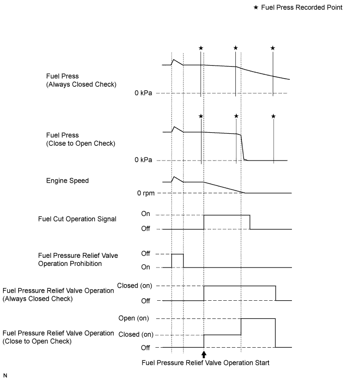
Malfunctions can be determined by checking the fuel pressure when performing a fuel cut and operating the pressure discharge valve with the intelligent tester.
-
During "Pressure Discharge Valve Check", the intelligent tester measures the fuel pressure while the engine is running, after the engine is stopped, and after the pressure discharge valve operates.
-
Connect the intelligent tester to the DLC3.
-
Turn the ignition switch to ON.
-
Turn the tester on.
Note
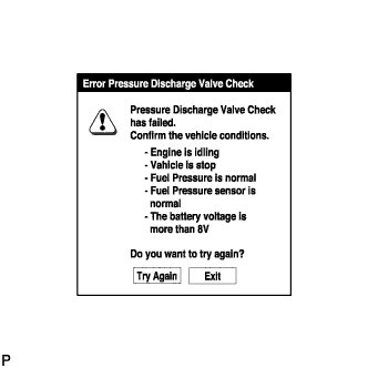
Confirm the following conditions:
-
Engine is idling.
-
Vehicle is stopped.
-
Fuel pressure is not extremely high (less than 100,000 kPa).
-
Fuel pressure sensor is normal.
-
Battery voltage is more than 8 V.
-
-
Select the following menus: Powertrain / Engine and ECT / Utility / Pressure Discharge Valve Check.
-
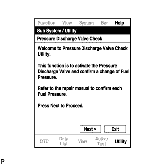
Press "Next".
-
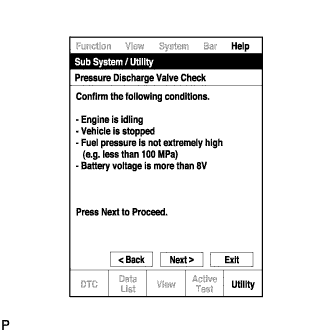
Press "Next" again to proceed.
-
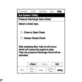
Select the "Pressure Discharge Valve Check" type.
Tech Tips
-
"Close to Open Check" opens the pressure discharge valve after the engine stops.
-
"Always Closed Check" holds the pressure discharge valve closed during the check.
-
-
Press "Next".
-
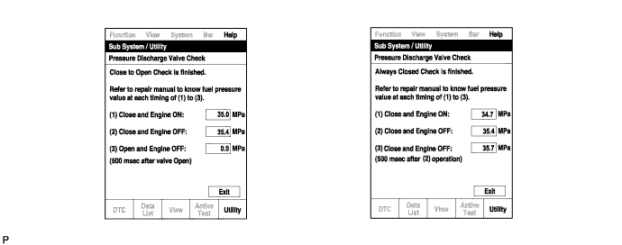
Perform troubleshooting based on the measurement results.
Tech Tips
-
During "Close to Open Check", if there is no large change in fuel pressure when the pressure discharge valve is closed while the engine is running and after the engine is stopped, and if the value is 0 kPa when the pressure discharge valve is open, the system is normal.
-
Perform "Always Closed Check" if the value is not 0 kPa when the pressure discharge valve is open during "Close to Open Check". If the results are the same as during "Close to Open Check", there is a pressure discharge valve operation malfunction.
-
If the fuel temperature is high, perform "Pressure Discharge Valve Check" after the fuel has cooled to the outside air temperature.
-
If a large amount of fuel is leaking, the fuel pressure decreases when the engine is stopped. However, the condition of the pressure discharge valve can still be determined by comparing the measurement results of "Close to Open Check" and "Always Closed Check".
-
-
-