ECD SYSTEM (w/ EGR Cooler Bypass Valve) Engine Knocking or Rattling
DESCRIPTION
| Malfunction Condition | Main Trouble Area | Related Trouble Area |
|---|---|---|
| Combustion in diesel engines takes place by means of self-ignition. If the timing of the ignition is delayed, the pressure inside the combustion chamber will increase too fast, which leads to uncontrolled combustion and can be heard as diesel knocking. If any of the following conditions are met, engine knocking may occur due to the fact that
|
|
|
Tech Tips
-
Specified values in the following troubleshooting flowchart are for reference only. Variations in the Data List values may occur depending on the measuring conditions or the vehicle's age. Do not judge the vehicle to be normal even when the Data List values indicate a standard level. There are possibly some concealed factors of the malfunction.
-
Check that the vehicle has not been modified in any way prior to the vehicle inspection.
INSPECTION PROCEDURE
Note
-
After replacing the supply pump assembly, the ECM needs initialization Click here.
-
After replacing the ECM, the new ECM needs registration Click here and initialization Click here.
PROCEDURE
-
CHECK SOUND AREA
-
Find the source of the abnormal sound using a mechanic's stethoscope.
Result Result Proceed to Combustion noise from engine A Noise from specific part B
B 
REPAIR OR REPLACE MALFUNCTIONING PARTS
A 
-
-
CHECK WIRE HARNESS IN ENGINE COMPARTMENT
-
Check the harness and connector connections of common rail system components.
OK The wire harnesses and connectors are connected securely
NG
REPAIR OR REPLACE HARNESS OR CONNECTOR
OK
-
-
CHECK AIR INTAKE SYSTEM
-
Check the air intake system (turbocharger sub-assembly, MAP sensor, and EGR valve etc.).
OK All hoses are connected securely, and also there are no leaks or blockage from air induction system
NG
REPAIR OR REPLACE AIR INTAKE SYSTEM
OK
-
-
READ OUTPUT DTCS (RELATING TO ENGINE)
-
Connect the intelligent tester to the DLC3.
-
Turn the ignition switch to ON and turn the tester on.
-
Select the following menus: Powertrain / Engine and ECT / DTC.
-
Read DTCs.
Result Result Proceed to No output A Engine related DTCs B
B
GO TO DTC CHART Click here
A
-
-
READ VALUE USING INTELLIGENT TESTER (MAP AND ATMOSPHERE PRESSURE)
-
Connect the intelligent tester to the DLC3.
-
Turn the ignition switch to ON and turn the tester on.
-
Select the following menus: Powertrain / Engine and ECT / Data List / MAP and Atmosphere Pressure.
-
Compare MAP to Atmosphere Pressure when the ignition switch is ON (do not start the engine).
Standard Difference between the MAP and the Atmosphere Pressure is less than 8 kPa Tech Tips
-
If MAP and Atmosphere Pressure have the same value, both are normal. If there is a difference of 8 kPa or more, compare the values to the atmospheric pressure for that day. The sensor whose deviation is the greatest is malfunctioning.
-
Standard atmospheric pressure is 101 kPa. For every 100 m increase in altitude, pressure drops by 1 kPa. Varies by weather.
Result Result Proceed to MAP and Atmosphere Pressure have the same value A MAP is different from actual atmospheric pressure B Atmosphere Pressure is different from actual atmospheric pressure C -
B
REPLACE MANIFOLD ABSOLUTE PRESSURE SENSOR Click here
C
REPLACE ECM Click here
A
-
-
PERFORM ACTIVE TEST USING INTELLIGENT TESTER (FUEL LEAK TEST)
Tech Tips
By performing this Active Test, the engine speed is maintained at high RPM and the common rail internal fuel pressure is raised to the maximum operating pressure. As a result, a fuel leak check can be conducted while retaining the high common rail pressure.
-
Connect the intelligent tester to the DLC3
-
Turn the ignition switch to ON and turn the tester on.
-
Select the following menus: Powertrain / Engine and ECT/ Active Test / Test the Fuel Leak / Data List / Fuel Press, Target Common Rail Pressure, and Target Pump SCV Current.
-
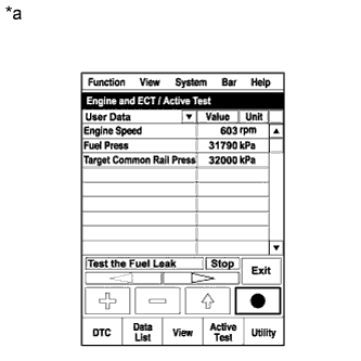
Text in Illustration *a Reference
Active Test Operation
Take a snapshot with the intelligent tester during the Active Test.
Tech Tips
Detailed graphs can be displayed by transferring the stored snapshot from the tester to a PC (personal computer) with Intelligent Viewer installed.
-
Measure the difference between the target fuel pressure (Target Common Rail Pressure) and the actual fuel pressure (Fuel Press) when the Active Test / Test the Fuel Leak is performed.
Tech Tips
To ensure accurate measurements, perform the Active Test with measurements 5 times or more.
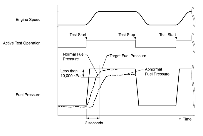
OK The difference between the target fuel pressure and the actual fuel pressure at 2 seconds after the Active Test starts is less than 10,000 kPa Tech Tips
-
The Target Common Rail Pressure means target fuel pressure controlled by the ECM.
-
The Fuel Press means actual fuel pressure.
-
If the pressure limiter mounted on the common rail assembly is malfunctioning, the actual fuel pressure will change as shown in [Pressure Limiter Malfunctioning] in the illustration.
-
If the pump is controlled using the active test [Test the Fuel Leak], when the active test is stopped, the actual fuel pressure may drop below the target common rail pressure, but this is normal and does not indicate a malfunction.
-
-
Read the value of Target Pump SCV current in Data List when the Active Test / Test the Fuel Leak is performed.
Standard Target Pump SCV Current is between 800 mA and 3,000 mA Tech Tips
If the value of Target Pump SCV Current stored in Freeze Frame Data is higher than standard, the intermittent suction control valve is probably stuck.
Result Result Proceed to Both results are within standard A Fuel pressure exceeds "Target Common Rail Pressure + 10,000 kPa" and / or Target Pump SCV Current value is out of standard range B Fuel pressure does not reach "Target Common Rail Pressure - 10,000 kPa" within 2 seconds C
B 
REPLACE SUCTION CONTROL VALVE Click here
C
BLEED AIR FROM FUEL SYSTEM Click here
A
-
-
CHECK INJECTOR COMPENSATION CODE
Note
Injector compensation codes are unique, 30-digit, and alphanumeric values printed on the head portion of each fuel injector assembly. If an incorrect injector compensation code is input into the ECM, the engine may rattle or engine idling may become rough. In addition, engine failure may occur and the life of the engine may be shortened.
-
Check the injector compensation code.
OK Compensation codes of the installed injectors are the same as the compensation codes registered in the ECM.
NG
REGISTER INJECTOR COMPENSATION CODE Click here
OK
-
-
RESET ECM
-
Disconnect the cable from the negative (-) battery terminal or remove the EFI fuse for at least 2 minutes.
-
Reconnect the cable to the negative (-) battery terminal.
-
Check whether the malfunction has been successfully repaired.
OK Malfunction has been repaired successfully
NG
READ VALUE USING INTELLIGENT TESTER (ACTIVATE THE VSV FOR EGR CUT) Click here
OK 
END
-
-
READ VALUE USING INTELLIGENT TESTER (ACTIVATE THE VSV FOR EGR CUT)
-
Connect the intelligent tester to the DLC3.
-
Start the engine and the turn the tester on.
-
Warm up the engine.
-
Turn the ignition switch off. Wait for 10 seconds and then restart the engine.
-
Select the following menus: Powertrain / Engine and ECT / Data List / MAF
-
Read the MAF value displayed on the tester when engine idling.
-
Select the following menus: Powertrain / Engine and ECT / Active Test / Activate The VSV for EGR Cut.
-
Read the MAF value when the VSV for EGR cut is turned from off to on using the Active Test function.
Tech Tips
-
If idling continues for 15 minutes or more, the EGR valve opening angle target becomes 0% (EGR valve fully closed). As this makes diagnosis impossible, it becomes necessary to run the vehicle or to restart the engine.
-
Before performing the diagnosis, confirm that the EGR valve opening angle target value is not 0%.
Result Active Test Result Proceed to Activate The VSV for EGR Cut.:
off (Open) to on (Close)
MAF value is not changed A MAF value is changed B Note
As the numerical values shown below may differ depending on the conditions such as the differences of measurements, the differences of measuring environments, and the changes of vehicle condition due to aging, do not determine with these values whether acceptable of not.
Tech Tips
The problem may be a temporary one, due to the entry of deposits or foreign matter. Please check that there are no deposits or foreign matter in the E-VRV or mass air flow meter.
Reference EGR Valve Condition (Opening) Measuring Condition MAF (Reference) Open (55%)
-
Atmosphere pressure: 101 kPa
-
Intake air temperature: 30°C (86°F)
-
Engine coolant temperature: 88°C (190°F)
3.0 to 9.0 g/sec Close (0%) 15 to 22 g/sec -
A
REPLACE ELECTRIC EGR CONTROL VALVE ASSEMBLY Click here
B
-
-
READ VALUE USING INTELLIGENT TESTER (EGR CLOSE LEARN VAL. AND EGR CLOSE LRN. STATUS)
-
Turn the ignition switch to ON.
-
Turn the ignition switch off, and wait for 15 seconds or more.
-
Connect the intelligent tester to the DLC3.
-
Turn the ignition switch to ON and turn the tester on.
-
Select the following menus: Powertrain / Engine and ECT/ Data List / EGR Close Learn Val. and EGR Close Lrn. Status.
-
Read values.
Standard EGR Close Lrn. Status is OK Tech Tips
-
When the EGR Close Lrn. Status is NG, the value of the EGR Close Learn Val. is unavailable because the EGR fully closed learn value is out of standard range.
-
When the EGR Close Lrn. Status is NG, the ECM suspends the learn value update. The value indicated on the tester is the past data when the EGR valve works properly or the initialized data remaining from when the battery cable was reconnected, i.e., the value is not current data.
-
As the EGR valve opens, the sensor output voltage decreases.
-
If the amount of EGR is insufficient, engine knocking may occur.
-
NG
INSPECT ELECTRIC EGR CONTROL VALVE ASSEMBLY Click here
OK
-
-
INSPECT DIESEL THROTTLE BODY ASSEMBLY
-
Inspect the diesel throttle body assembly (using intelligent tester).
-
Turn the ignition switch to ON.
-
Turn the ignition switch off and wait for 5 seconds or more.
Tech Tips
Be sure to turn off the ignition switch before performing this inspection. The fully closed position of the diesel throttle valve is learned when the ignition switch is turned off.
-
Connect the intelligent tester to the DLC3.
-
Turn the ignition switch to ON and turn the tester on.
-
Select the following menus: Powertrain / Engine and ECT / Data List / Actual Throttle Position.
-
Read values.
Standard Engine Condition Specified Condition Ignition switch ON 0% Idling (after engine warmed up, at an altitude near sea level) 70 to 90% Accelerator pedal fully depressed 0%
and value changes smoothly in transition
Tech Tips
-
Check the Throttle Motor DUTY in the Data List items at the same time. If the value in Throttle Motor DUTY is outside the range of 50 +/-40% for 30 seconds or more, the throttle valve may not be sliding properly.
-
The Actual Throttle Position in the Data List items is indicated as follows:
Standard Throttle Valve Condition Actual Throttle Position Fully closed 100% Fully open 0% -
-
Select the following menus: Powertrain / Engine and ECT/ Data List / Throttle Close Learning Val. and Diesel Throttle Learn Status.
-
Read values when the ignition switch is ON.
OK Diesel Throttle Learn Status is OK Note
Extremely cold conditions might cause the throttle valve movement to be delayed.
Tech Tips
-
When the Diesel Throttle Learn Status is NG, the value of the Throttle Close Learning Val. is unavailable because the throttle fully closed learn value is out of standard range.
-
When the Diesel Throttle Learn Status is NG, the ECM suspends the learn value update. The value indicated on the tester is the past data when the diesel throttle works properly or the initialized data remaining from when the battery cable was reconnected. i.e., the value is not current data.
-
If the diesel throttle condition is normal the fully closed position is learned when the ignition switch is turned off and 5 seconds or more elapse.
-
-
-
Inspect the diesel throttle body assembly (does not use intelligent tester).
-
Inspect throttle valve operation visually.
Tech Tips
For related procedures, refer to the appropriate repair manuals.
OK No malfunction -
NG
REPLACE DIESEL THROTTLE BODY ASSEMBLY Click here
OK
-
-
CHECK THE TEMPERATURE WHEN KNOCKING OCCURS
-
Check the temperature when knocking trouble occurs.
Result Result Proceed to Knocking only for cold engine A Knocking both for cold and warmed up engine B
B
READ VALUE USING INTELLIGENT TESTER (MAP AND MAF) Click here
A
-
-
INSPECT ENGINE COOLANT TEMPERATURE SENSOR
-
After warming up the engine, the engine coolant temperature should be 70°C (158°F) or more. After leaving the vehicle overnight, the engine coolant temperature should be nearly equal to the intake air temperature.
OK The engine coolant temperature is nearly equal to the intake air temperature Tech Tips
If the engine coolant temperature sensor output is less than the actual engine coolant temperature, engine knocking may occur.
NG
REPLACE ENGINE COOLANT TEMPERATURE SENSOR Click here
OK
-
-
INSPECT GLOW PLUG ASSEMBLY (RESISTANCE)
-
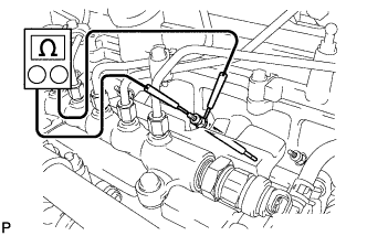
Disconnect the glow plug assembly connector.
-
Measure the resistance according to the values in the table below.
Standard resistance Tester Connection Condition Specified Condition Glow plug terminal - Body ground 20°C (68°F) Approximately 0.7 Ω Tech Tips
If any of the glow plug assembly has an open circuit, the engine power will be insufficient only when the engine is cold.
Note
-
Exercise extreme care not to damage the glow plug pipes. Damaging them could cause an open circuit or shorten the life of the glow plug assembly.
-
Keep the glow plug assembly free of oil and fuel while cleaning.
-
Wipe any oil off of the terminal and Bakelite washer with a clean, dry cloth during inspection.
-
Do not apply more than 11 V to the glow plug assembly as it may cause an open circuit.
-
NG
REPLACE GLOW PLUG ASSEMBLY Click here
OK
-
-
READ VALUE USING INTELLIGENT TESTER (INJECTOR FEEDBACK VAL #1 TO #4)
Tech Tips
-
Read values of the Injector Feedback Val. #1 to #4 when the engine is cold.
-
If the engine coolant temperature is more than 40°C, leave the vehicle until the engine coolant reaches almost the same temperature as the atmosphere temperature.
-
Connect the intelligent tester to the DLC3.
-
Turn the ignition switch to ON and the tester on.
-
Select the following menus: Powertrain / Engine and ECT / Data List / Injector Feedback Val. #1 to #4.
-
Start the engine.
-
Read values during engine idling when it is cold, and write them down.
Standard Tester Display Condition Specified Condition Injector Feedback Val. #1
Injector Feedback Val. #2
Injector Feedback Val. #3
Injector Feedback Val. #4
Idling with cold engine Less than 3.0 mm3/st
Note
If any of the Injector Feedback Values are outside of the specified range, and there is no problem with the cylinder compression pressure, replace all of the fuel injectors together.
NG
REPLACE FUEL INJECTOR ASSEMBLY Click here
OK
-
-
READ VALUE USING INTELLIGENT TESTER (MAP AND MAF)
-
Connect the intelligent tester to the DLC3.
-
Start the engine, warm it up, and turn the tester on.
-
Select the following menus: Powertrain / Engine and ECT / Data List / MAP and MAF.
Standard Item Engine Speed*1 Standard Range Description MAP*2 Ignition switch ON (engine stopped) Same as atmospheric pressure Intake manifold internal pressure detected by manifold absolute pressure sensor Idling 94 to 104 kPa (705 to 780 mmHg, 27.7 to 30.7 in.Hg) 3,000 rpm (no engine load) 111 to 141 kPa (837 to 1,058 mmHg, 32.7 to 41.6 in.Hg MAF*2 Ignition switch ON (engine stopped) Less than 0.5 g/s Intake air volume detected by mass air flow meter assembly Idling 3 to 9 g/s 3,000 rpm (no engine load) 30 to 50 g/s Result Item Result Proceed to MAP and MAF Within standard range A Outside standard range B Only MAP Outside standard range C Only MAF Outside standard range D Tech Tips
*1: The A/C switch and all accessory switches should be off with a fully warm engine.
*2: This value is indicated when the ambient temperature is 25°C (77°F) and the atmospheric pressure is 101 kPa (758 mmHg, 29.83 in.Hg), and a stable boost pressure is maintained for approximately 10 seconds.
B
CHECK AIR INDUCTION SYSTEM (REFER TO STEP 3)
C
GO TO DTC P0107 AND P0108 (RELATED TO MANIFOLD ABSOLUTE PRESSURE SENSOR) Click here
D
GO TO P0101, P0102 AND P0103 (RELATED TO MASS AIR FLOW METER) Click here
A
-
-
INSPECT ELECTRIC EGR CONTROL VALVE ASSEMBLY
-
Remove the electric EGR control valve assembly.
-
Check that the EGR valve is fully closed.
OK The EGR valve fully closes Tech Tips
-
Hold the EGR valve to a light and confirm that the valve contacts with the valve seat securely.
-
If light leaks out from the valve, the EGR valve does not close completely.
-
Remove the deposit if there is much deposit in the EGR valve or the passage of the intake manifold.
-
NG
REPLACE ELECTRIC EGR CONTROL VALVE ASSEMBLY Click here
OK
-
-
BASIC INSPECTION
-
Check the fuel quality.
-
Check the fuel for air.
-
Check the fuel system for blockages.
-
Check the air filter.
-
Check the engine oil.
-
Check the engine idling speed and the maximum engine speed.
-
Check the vacuum pump assembly.
NG
REPAIR OR REPLACE MALFUNCTIONING PARTS
OK
-
-
CONFIRM WHETHER MALFUNCTION HAS BEEN SUCCESSFULLY REPAIRED
-
Check whether the knocking has been successfully repaired.
NG
READ VALUE USING INTELLIGENT TESTER (INJECTION VOLUME AND INJECTOR FEEDBACK VAL #1 TO #4) Click here
OK
END
-
-
READ VALUE USING INTELLIGENT TESTER (INJECTION VOLUME AND INJECTOR FEEDBACK VAL #1 TO #4)
-
Connect the intelligent tester to the DLC3.
-
Start the engine and warm it up until the engine coolant temperature reaches 75°C (167°F) or higher.
-
Allow the engine to idle for 1 minute or more.
Tech Tips
The A/C switch and all accessory switches should be off with a fully warm engine.
-
Turn the tester on.
-
Select the following menus: Powertrain / Engine and ECT / Data List / Injection Volume and Injector Feedback Val. #1 to #4.
-
Read values during engine idling.
Standard Tester Display Condition Specified Condition Injection Volume Idling Less than 10.0 mm3/st
Injector Feedback Val. #1
Injector Feedback Val. #2
Injector Feedback Val. #3
Injector Feedback Val. #4
Idling Less than 3.0 mm3/st
Note
If any of the Injector Feedback Values are outside of the specified range, and there is no problem with the cylinder compression pressure, replace all of the fuel injectors together.
NG
REPLACE FUEL INJECTOR ASSEMBLY Click here
OK
END
-
-
BLEED AIR FROM FUEL SYSTEM
-
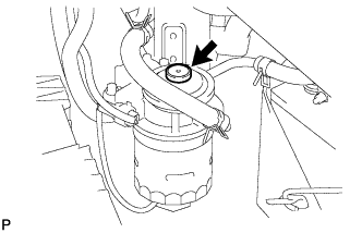
Using a hand pump mounted on the fuel filter cap, bleed the air from the fuel system. Continue pumping until the pump resistance increases.
Note
-
Hand pump pumping speed: Max. 2 strokes/sec.
-
The hand pump must be pushed full stroke during pumping.
-
When the fuel pressure at the supply pump inlet port reaches a saturated pressure, the hand pump resistance increases.
-
If pumping is interrupted during the air bleeding process, fuel in the fuel line may return to the fuel tank sub-assembly. Continue pumping until the hand pump resistance increases.
-
If the hand pump resistance does not increase despite consecutively pumping 200 times or more, there may be a fuel leak between the fuel tank sub-assembly and fuel filter assembly, the hand pump may be malfunctioning, or the vehicle may have run out of fuel.
-
If a large amount of air remains inside the fuel system, the common rail pressure does not rise to the pressure range necessary for normal use, and the engine cannot be started.
-
-
Start the engine.
Note
-
If a large amount of air remains inside the fuel system, the starter may need to be cranked for 10 seconds or more to start the engine.
-
Do not crank the engine continuously for more than 20 seconds. The battery may be discharged.
-
Use a fully-charged battery.
-
When the engine can be started, proceed to the next step.
-
If the engine cannot be started, bleed the air again using the hand pump until the hand pump resistance increases (refer to step (a)). Then start the engine.
-
-
Turn the ignition switch off.
-
Connect the intelligent tester to the DLC3.
-
Turn the ignition switch to ON and turn the tester on.
-
Start the engine.
-
Select the following menus: Powertrain / Engine and ECT / Active Test / Test the Fuel Leak.
-
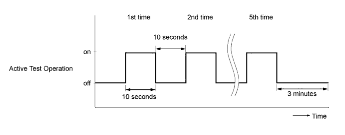
Perform the following test 5 times with on/off intervals of 10 seconds : Active Test / Test the Fuel Leak.
Text in Illustration *a Reference
Active Test Operation
-
Allow the engine to idle for 3 minutes or more after performing the Active Test.
NEXT
-
-
PERFORM ACTIVE TEST USING INTELLIGENT TESTER (FUEL LEAK TEST)
Tech Tips
By performing this Active Test, the engine speed is maintained at high RPM and the common rail internal fuel pressure is raised to the maximum operating pressure. As a result, a fuel leak check can be conducted while retaining the high common rail pressure.
-
Connect the intelligent tester to the DLC3.
-
Turn the ignition switch to ON and turn the tester on.
-
Select the following menus: Powertrain / Engine and ECT/ Active Test / Test the Fuel Leak / Data List / Fuel Press, Target Common Rail Pressure, and Target Pump SCV Current.
-
Text in Illustration *a Reference
Active Test Operation
Take a snapshot with the intelligent tester during the Active Test.
Tech Tips
Detailed graphs can be displayed by transferring the stored snapshot from the tester to a PC (personal computer) with Intelligent Viewer installed.
-
Measure the difference between the target fuel pressure (Target Common Rail Pressure) and the actual fuel pressure (Fuel Press) when the Active Test / Test the Fuel Leak is performed.
Tech Tips
To ensure accurate measurements, perform the Active Test with measurements 5 times or more.
OK The difference between the target fuel pressure and the actual fuel pressure at 2 seconds after the Active Test starts is less than 10,000 kPa Tech Tips
-
The Target Common Rail Pressure means target fuel pressure controlled by the ECM.
-
The Fuel Press means actual fuel pressure.
-
If the pressure limiter mounted on the common rail assembly is malfunctioning, the actual fuel pressure will change as shown in [Pressure Limiter Malfunctioning] in the illustration.
-
Under normal conditions, the pressure limiter opens and relieves abnormal high-pressure to the return pipe when the fuel pressure inside the common rail assembly reaches to 190 MPa. If the actual fuel pressure suddenly drops to 40 to 50 MPa despite the fuel pressure inside the common rail assembly not reaching to 190 MPa, replace the common rail assembly because the pressure limiter opening pressure is probably deteriorated.
-
If the pump is controlled using the active test [Test the Fuel Leak], when the active test is stopped, the actual fuel pressure may drop below the target common rail pressure, but this is normal and does not indicate a malfunction.
-
NG
CONFIRM IF FUEL BEING SUPPLIED TO SUPPLY PUMP ASSEMBLY Click here
OK
-
-
CONFIRM WHETHER MALFUNCTION HAS BEEN SUCCESSFULLY REPAIRED
-
Check whether the knocking has been successfully repaired.
NEXT
END
-
-
CONFIRM IF FUEL BEING SUPPLIED TO SUPPLY PUMP ASSEMBLY
-
Disconnect the inlet hose from the supply pump assembly.
-
Operate the hand pump and check that fuel is being supplied to the supply pump assembly.
OK Fuel is properly supplied to the supply pump assembly when the hand pump is operated Tech Tips
-
When there is a lack of fuel, fuel pressure drops.
-
Check that the fuel filter assembly is not clogged.
-
NG
REPAIR OR REPLACE CLOGGED FUEL PIPE (INCLUDING FUEL FREEZING) (FUEL TANK - SUPPLY PUMP ASSEMBLY) OR FUEL FILTER ASSEMBLY
OK
-
-
REPLACE SUCTION CONTROL VALVE
-
Replace the suction control valve. Click here
NEXT
-
-
BLEED AIR FROM FUEL SYSTEM
-
Referring to step 21, bleed the air from the fuel system.
NEXT
-
-
PERFORM FUEL SUPPLY PUMP INITIALIZATION
-
Perform supply pump initialization. Click here
NEXT
-
-
PERFORM ACTIVE TEST USING INTELLIGENT TESTER (FUEL LEAK TEST)
Tech Tips
By performing this Active Test, the engine speed is maintained at high RPM and the common rail internal fuel pressure is raised to the maximum operating pressure. As a result, a fuel leak check can be conducted while retaining the high common rail pressure.
-
Connect the intelligent tester to the DLC3.
-
Turn the ignition switch to ON and turn the tester on.
-
Select the following menus: Powertrain / Engine and ECT/ Active Test / Test the Fuel Leak / Data List / Fuel Press, Target Common Rail Pressure, and Target Pump SCV Current.
-
Text in Illustration *a Reference
Active Test Operation
Take a snapshot with the intelligent tester during the Active Test.
Tech Tips
Detailed graphs can be displayed by transferring the stored snapshot from the tester to a PC (personal computer) with Intelligent Viewer installed.
-
Measure the difference between the target fuel pressure (Target Common Rail Pressure) and the actual fuel pressure (Fuel Press) when the Active Test / Test the Fuel Leak is performed.
Tech Tips
To ensure accurate measurements, perform the Active Test with measurements 5 times or more.
OK The difference between the target fuel pressure and the actual fuel pressure at 2 seconds after the Active Test starts is less than 10,000 kPa Tech Tips
-
The Target Common Rail Pressure means target fuel pressure controlled by the ECM.
-
The Fuel Press means actual fuel pressure.
-
If the pressure limiter mounted on the common rail assembly is malfunctioning, the actual fuel pressure will change as shown in [Pressure Limiter Malfunctioning] in the illustration.
-
Under normal conditions, the pressure limiter opens and relieves abnormal high-pressure to the return pipe when the fuel pressure inside the common rail assembly reaches to 190 MPa. If the actual fuel pressure suddenly drops to 40 to 50 MPa despite the fuel pressure inside the common rail assembly not reaching to 190 MPa, replace the common rail assembly because the pressure limiter opening pressure is probably deteriorated.
-
If the pump is controlled using the active test [Test the Fuel Leak], when the active test is stopped, the actual fuel pressure may drop below the target common rail pressure, but this is normal and does not indicate a malfunction.
Result Result Proceed to Outside standard range A Within standard range B -
B
CONFIRM WHETHER MALFUNCTION HAS BEEN SUCCESSFULLY REPAIRED Click here
A
-
-
REPLACE COMMON RAIL ASSEMBLY
-
Replace the common rail assembly. Click here
NEXT
-
-
BLEED AIR FROM FUEL SYSTEM
-
Referring to step 21, bleed the air from the fuel system.
NEXT
-
-
CONFIRM WHETHER MALFUNCTION HAS BEEN SUCCESSFULLY REPAIRED
-
Check whether the knocking has been successfully repaired by starting the engine.
NEXT
END
-
-
REPLACE FUEL INJECTOR ASSEMBLY
-
Replace all of the fuel injector assemblies. Click here
NEXT
-
-
REGISTER INJECTOR COMPENSATION CODE
Note
Injector compensation codes are unique, 30-digit, and alphanumeric values printed on the head portion of each fuel injector assembly. If an incorrect injector compensation code is input into the ECM, the engine may rattle or engine idling may become rough. In addition, engine failure may occur and the life of the engine may be shortened.
-
Register the injector compensation code. Click here
NEXT
-
-
BLEED AIR FROM FUEL SYSTEM
-
Referring to step 21, bleed the air from the fuel system.
NEXT
-
-
CONFIRM WHETHER MALFUNCTION HAS BEEN SUCCESSFULLY REPAIRED
-
Check whether the knocking has been successfully repaired.
NEXT
END
-