ECD SYSTEM (w/ EGR Cooler Bypass Valve) Rough Idling or Excessive Engine Vibrations
DESCRIPTION
| Malfunction Condition | Main Trouble Areas | Related Trouble Areas |
|---|---|---|
|
|
|
Tech Tips
-
Rough idling and excessive engine vibrations are checked in this troubleshooting procedure.
-
Specified values in the following troubleshooting flowchart are for reference only. Variations in the Data List result values may occur depending on the measuring conditions or the vehicle's age. Do not judge the vehicle to be normal even when the Data List values indicate a standard level. There are possibly some concealed factors of the malfunction.
-
Check that the vehicle has not been modified in any way prior to the vehicle inspection.
INSPECTION PROCEDURE
Note
-
After replacing the ECM, the new ECM needs registration Click here and initialization Click here.
-
After replacing the supply pump assembly, the ECM needs initialization. Click here
-
After replacing the fuel injector assembly, the ECM needs registration. Click here
Tech Tips
Before troubleshooting, conduct the following:
-
(a)Check the fuel quality.
-
(b)Check the fuel for air.
-
(c)Check the fuel system for blockages.
-
(d)Check the air filter.
-
(e)Check the engine oil.
-
(f)Check the engine coolant.
-
(g)Check the engine idling speed and the maximum engine speed.
-
(h)Check the vacuum pump assembly.
PROCEDURE
-
CHECK MALFUNCTION CONDITION
-
Identify when shuddering occurs.
Result Driving Condition Proceed to When idling A When engaging engine clutch at vehicle start B
(Clutch system shudders)
B 
REPAIR OR REPLACE CLUTCH SYSTEM
A 
-
-
CHECK WIRE HARNESS AND CONNECTION IN ENGINE COMPARTMENT
-
Check the wire harness and connector connections of common rail system components.
OK The wire harnesses and connectors are connected securely. Tech Tips
The engine may have problems when there is an intermittent disconnection in a circuit related to the fuel pressure sensor, crankshaft position sensor, engine coolant temperature sensor etc.
NG 
REPAIR OR REPLACE HARNESS AND CONNECTOR Click here
OK
-
-
READ OUTPUT DTC (RELATING TO ENGINE)
-
Connect the intelligent tester to the DLC3.
-
Turn the ignition switch to ON and turn the tester on.
-
Enter the following menus: Powertrain / Engine and ECT / DTC.
-
Read pending DTCs.
Result Result Proceed to No DTCs are output A Engine related DTCs are output B
B
GO TO DTC CHART Click here
A
-
-
TAKE SNAPSHOT DURING IDLING (PROCEDURE 4)
-
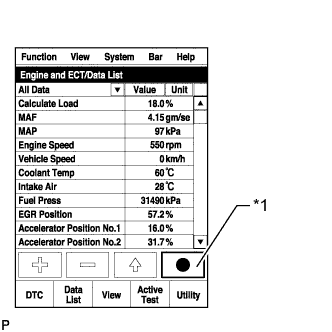
Text in Illustration *1 Snapshot Button Connect the intelligent tester to the DLC3.
-
Start the engine and turn the tester on.
-
Enter the following menus: Powertrain / Engine and ECT / Data List / All Data.
-
Take a snapshot when idling with no load after the engine is warmed up until the engine coolant temperature reaches 70°C (158°F) or higher. Allow the engine to idle for 1 minute to more.
Tech Tips
-
A snapshot can be used to compare vehicle data from the time of the malfunction to normal data and is very useful for troubleshooting.
-
Graphs can be displayed by transferring the stored snapshot data from the tester to a PC. Intelligent Viewer must be installed on the PC.
-
The shift lever should be in neutral and the A/C switch and all accessory switches should be off.
-
NEXT
-
-
CHECK WHITE SMOKE
-
Check the white smoke.
Result Result Proceed to White smoke emitted from exhaust pipe after starting engine B Except above A
B
CHECK AND REPAIR OR REPLACE ENGINE ASSEMBLY Click here
A
-
-
CHECK DATA LIST (ENGINE SPEED)
-
Check engine speed in the snapshot taken at procedure 4 when the engine was idling.
Result Result Proceed to Change in engine speed coincides with air conditioning system operation B Except above A
B
CHECK AIR CONDITIONING SYSTEM Click here
A
-
-
CHECK DATA LIST (INJECTION FEEDBACK VAL #1 TO #4 AND INJECTION VOLUME)
-
Check Injection Feedback Val # in the snapshot taken when the engine was idling.
Result Result Proceed to Injection Feedback Val for at least one cylinder is more than 3 mm3/st and engine vibration is abnormally large
A Except above B Tech Tips
-
When there is a problem with the operation of a fuel injector due to foreign matter in the inside of the fuel injector, etc., the fuel injection volume decreases. As a result, the ECM gives instructions to increase the fuel injection volume, which causes Injection Feedback Val to increase.
-
The ECM controls the system so that the sum of Injection Feedback Val for all of the cylinders is approximately 0 mm3/st. Even if the value of Injection Feedback Val for a cylinder is less than -3.0 mm3/st (-3.0 mm3/st is the lowest value indicating a normal condition), as long as the value of Injection Feedback Val for each of the other cylinders is 3.0 mm3/st or less, the fuel injectors are not malfunctioning.
-
B
CHECK DATA LIST (FUEL PRESS AND TARGET COMMON RAIL PRESSURE) Click here
A
-
-
INSPECT INJECTOR COMPENSATION CODE
-
Read the injector compensation code Click here.
OK Compensation codes stored in the ECM match compensation codes of the installed fuel injectors.
NG
REGISTER INJECTOR COMPENSATION CODE AND PERFORM PILOT QUALITY LEARNING Click here
OK
-
-
CLEAN OR REPLACE FUEL FILTER
-
Clean or replace the fuel filter.
Tech Tips
Be sure to clean the inside of the fuel filter case as the fuel injectors may not operate properly if the fuel filter is installed with foreign matter remaining inside the fuel filter case.
NEXT
-
-
BLEED AIR FROM FUEL SYSTEM
-
Bleed the air from the fuel system Click here.
NEXT
-
-
PERFORM ACTIVE TEST USING INTELLIGENT TESTER (CONTROL THE CYLINDER #1 TO #4 FUEL CUT)
Tech Tips
Use this Active Test to determine the malfunctioning cylinder.
-
Connect the intelligent tester to the DLC3.
-
Start the engine and turn the tester on.
-
Enter the following menus: Powertrain / Engine and ECT / Active Test / Control the Cylinder #1 to #4 Fuel Cut.
Tech Tips
-
If the engine idle speed does not change when a fuel injector is disabled, the cylinder being tested is malfunctioning.
-
If the cylinder being tested is normal, there will be a significant change in idle speed when the fuel injection is stopped for that cylinder.
-
NEXT
-
-
REPLACE FUEL INJECTOR OF MALFUNCTIONING CYLINDER
-
Replace the fuel injector of the malfunctioning cylinder Click here.
NEXT
-
-
BLEED AIR FROM FUEL SYSTEM
-
Bleed the air from the fuel system Click here.
NEXT
-
-
REGISTER INJECTOR COMPENSATION CODE AND PERFORM PILOT QUALITY LEARNING
-
Register the injector compensation code Click here.
-
Perform the fuel injector pilot quantity learning Click here.
NEXT
CONFIRM WHETHER MALFUNCTION HAS BEEN SUCCESSFULLY REPAIRED Click here
-
-
REPAIR OR REPLACE HARNESS AND CONNECTOR
-
Repair or replace the harness or connector.
NEXT
CONFIRM WHETHER MALFUNCTION HAS BEEN SUCCESSFULLY REPAIRED Click here
-
-
CHECK AND REPAIR OR REPLACE ENGINE ASSEMBLY
-
Check the following items, and repair or replace the malfunctioning part if necessary.
-
Check cylinder compression pressure Click here.
-
Inspect the glow plug assembly Click here.
-
NEXT
CONFIRM WHETHER MALFUNCTION HAS BEEN SUCCESSFULLY REPAIRED Click here
-
-
CHECK AIR CONDITIONING SYSTEM
-
Check the air conditioning system Click here.
NEXT
-
-
CONFIRM WHETHER MALFUNCTION HAS BEEN SUCCESSFULLY REPAIRED
NEXT 
END
-
CHECK DATA LIST (FUEL PRESS AND TARGET COMMON RAIL PRESSURE)
-
Check Fuel Press and Target Common Rail Pressure in the snapshot taken when the engine was idling.
Result Result Proceed to Fuel Press is outside range of +/-5000 kPa from Target Common Rail Pressure A Except above B
B
PERFORM ACTIVE TEST USING INTELLIGENT TESTER (ACTIVATE THE VSV FOR EGR CUT) Click here
A
-
-
CHECK HARNESS AND CONNECTOR (SUCTION CONTROL VALVE - ECM)
-
Disconnect the S11 suction control valve connector.
-
Disconnect the E11 ECM connector.
-
Measure the resistance according to the value(s) in the table below.
Standard Resistance (Check for Open) Tester Connection Condition Specified Condition S11-1 - E11-23(PCV+) Always Below 1 Ω S11-2 - E11-12(PCV-) Always Below 1 Ω Standard Resistance (Check for Short) Tester Connection Condition Specified Condition S11-1 or E11-23(PCV+) - Body ground Always 10 kΩ or higher S11-2 or E11-12(PCV-) - Body ground Always 10 kΩ or higher
NG
REPAIR OR REPLACE HARNESS AND CONNECTOR Click here
OK
-
-
CHECK IF FUEL IS BEING SUPPLIED TO FUEL SUPPLY PUMP
-
Disconnect the inlet hose from the fuel supply pump.
-
Operate the priming pump and check that fuel is being supplied to the fuel supply pump.
OK Fuel is properly supplied to the fuel supply pump when the priming pump is operated. Tech Tips
-
When there is a lack of fuel, the fuel pressure drops.
-
Inspect for fuel filter clogging.
(Check that the fuel filter is not clogged.)
-
NG
CHECK AND REPAIR OR REPLACE CLOGGED FUEL PIPE (INCLUDING FROZEN FUEL) (FUEL TANK - FUEL SUPPLY PUMP) Click here
OK
-
-
REPLACE SUCTION CONTROL VALVE
-
Replace the suction control valve Click here.
NEXT
-
-
BLEED AIR FROM FUEL SYSTEM
-
Bleed the air from the fuel system Click here.
NEXT
-
-
PERFORM FUEL SUPPLY PUMP INITIALIZATION
-
Perform fuel supply pump initialization Click here.
NEXT
CONFIRM WHETHER MALFUNCTION HAS BEEN SUCCESSFULLY REPAIRED Click here
-
-
REPAIR OR REPLACE HARNESS AND CONNECTOR
-
Repair or replace the harness or connector.
NEXT
CONFIRM WHETHER MALFUNCTION HAS BEEN SUCCESSFULLY REPAIRED Click here
-
-
CHECK AND REPAIR OR REPLACE CLOGGED FUEL PIPE (INCLUDING FROZEN FUEL) (FUEL TANK - FUEL SUPPLY PUMP)
-
Check and replace clogged the fuel pipe.
NEXT
-
-
BLEED AIR FROM FUEL SYSTEM
-
Bleed the air from the fuel system Click here.
NEXT
-
-
CONFIRM WHETHER MALFUNCTION HAS BEEN SUCCESSFULLY REPAIRED
NEXT
END
-
PERFORM ACTIVE TEST USING INTELLIGENT TESTER (ACTIVATE THE VSV FOR EGR CUT)
-
Connect the intelligent tester to the DLC3.
-
Turn the ignition switch to ON and turn the tester on.
-
Enter the following menus: Powertrain / Engine and ECT / Active Test / Activate the VSV for EGR Cut.
-
Check the MAF during the Active Test.
Result Result Proceed to When EGR is cut, MAF value is constant at 15 to 22 g/sec., or when EGR is not cut, MAF value is 3 to 9 g/sec. or less A Except above B
B
CHECK AND REPLACE ENGINE MOUNTING INSULATOR Click here
A
-
-
CHECK FOR DEPOSIT (ELECTRIC EGR CONTROL VALVE ASSEMBLY)
-
Remove the electric EGR control valve assembly.
-
Visually check the electric EGR control valve assembly for deposits.
If there are deposits, clean the electric EGR control valve assembly.
Tech Tips
-
If the EGR valve is stuck closed, the intake air amount increases and engine vibration may worsen.
-
If the EGR valve does not operate due to clogging or disconnection of the vacuum hose, repair the hose.
-
If the EGR valve does not close properly or is stuck open, EGR becomes excessive and combustion becomes unstable. Also, there may be a lack of power.
-
If there is an extremely large amount of deposit in the EGR valve, the EGR valve should be replaced.
-
NEXT
CONFIRM WHETHER MALFUNCTION HAS BEEN SUCCESSFULLY REPAIRED Click here
-
-
CHECK AND REPLACE ENGINE MOUNTING INSULATOR
-
Check the following items, and repair or replace the malfunctioning part if necessary.
-
Check that the engine mounting insulators are installed correctly.
-
Check that the engine mounting insulators are not twisted.
-
Check that deformation of an engine mounting insulator is not causing the engine to contact the vehicle body.
-
NEXT
-
-
CONFIRM WHETHER MALFUNCTION HAS BEEN SUCCESSFULLY REPAIRED
NEXT
END