ECD SYSTEM (w/ EGR Cooler Bypass Valve), Diagnostic DTC:P245C, P245D
| DTC Code | DTC Name |
|---|---|
| P245C | EGR Cooler Bypass Control Circuit Low |
| P245D | EGR Cooler Bypass Control Circuit High |
DESCRIPTION
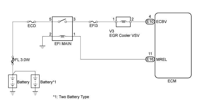
The EGR cooler VSV is controlled by the ECM, and the opening and closing of the EGR cooler bypass valve is performed according to the vacuum applied by the vacuum pump assembly.
| DTC No. | DTC Detection Condition | Trouble Area |
|---|---|---|
| P245C | Open in the EGR cooler VSV circuit for 3 seconds (1 trip detection logic) |
|
| P245D | Short in the EGR cooler VSV circuit for 3 seconds (1 trip detection logic) |
|
WIRING DIAGRAM
INSPECTION PROCEDURE
Note
After replacing the ECM, the new ECM needs registration Click here and initialization Click here.
Tech Tips
Read freeze frame data using the intelligent tester. Freeze frame data records the engine conditions when a malfunction is detected. When troubleshooting, freeze frame data can help determine if the vehicle was running or stopped, if the engine was warmed up or not, and other data from the time the malfunction occurred.
PROCEDURE
-
INSPECT EGR COOLER VSV (RESISTANCE)
-
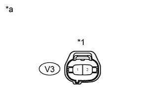
Text in Illustration *1 EGR Cooler VSV *a Component Side Disconnect the V3 EGR cooler VSV connector.
-
Measure the resistance of the EGR cooler VSV.
Standard resistance Tester Connection Condition Specified Condition 1 - 2 20°C (68°F) 33 to 39 Ω
NG 
REPLACE EGR COOLER VSV Click here
OK 
-
-
INSPECT EGR COOLER VSV (POWER SOURCE VOLTAGE)
-
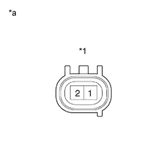
Text in Illustration *1 EGR Cooler VSV Connector *a Wire Harness Side Disconnect the V3 EGR cooler VSV connector.
-
Turn the ignition switch to ON.
-
Measure the voltage of the wire harness side connector and body ground.
Standard voltage Tester Connection Specified Condition V3-1 - Body ground 11 to 14 V
NG 
CHECK HARNESS AND CONNECTOR (EFI MAIN RELAY - EGR COOLER VSV) Click here
OK
-
-
CHECK HARNESS AND CONNECTOR (EGR COOLER VSV - ECM)
-
Disconnect the V3 EGR cooler VSV connector.
-
Disconnect the E10 ECM connector.
-
Measure the resistance of the wire harness side connector.
Standard resistance (Check for open) Tester Connection Specified Condition V3-2 - E10-4 (ECBV) Below 1 Ω Standard resistance (Check for short) Tester Connection Specified Condition V3-2 or E10-4 (ECBV) - Body ground 10 kΩ or higher
NG
REPAIR OR REPLACE HARNESS OR CONNECTOR
OK 
REPLACE ECM Click here
-
-
CHECK HARNESS AND CONNECTOR (EFI MAIN RELAY - EGR COOLER VSV)
-
Inspect the EFI3 fuse.
-
Remove the EFI3 fuse from the R/B No. 2.
-
Check the EFI3 fuse resistance.
Standard resistance Below 1 Ω -
Reinstall the EFI3 fuse.
-
-
Check the wire harness between the EGR cooler VSV and EFI MAIN relay.
-
Disconnect the V3 EGR cooler VSV connector.
-
Remove the EFI MAIN relay from the R/B No. 2.
-
Check the resistance.
Standard resistance (Check for open) Tester Connection Specified Condition R/B No. 2 (EFI MAIN relay terminal 3) - V3-1 Below 1 Ω Standard resistance (Check for short) Tester Connection Specified Condition R/B No. 2 (EFI MAIN relay terminal 3) or V3-1 - Body ground 10 kΩ or higher -
Reconnect the EGR cooler VSV connector.
-
Reinstall the EFI MAIN relay.
-
NG
REPAIR OR REPLACE HARNESS OR CONNECTOR
OK
INSPECT ECM POWER SOURCE CIRCUIT Click here
-