ECD SYSTEM (w/ EGR Cooler Bypass Valve) MIL Circuit
DESCRIPTION
If the ECM detects a malfunction, the MIL illuminates. The ECM then records the DTC in its memory.
WIRING DIAGRAM
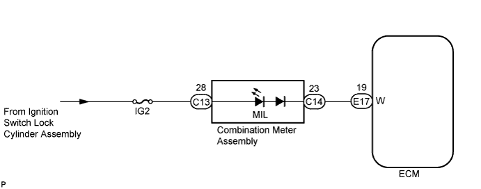
INSPECTION PROCEDURE
Note
After replacing the ECM, the new ECM needs registration Click here and initialization Click here.
PROCEDURE
-
CHECK MIL
Tech Tips
Use the table below to troubleshoot each problem symptom.
Reference Condition Proceed to MIL remains on A MIL is not illuminated B
B 
CHECK IF MIL ILLUMINATES Click here
A 
-
CHECK IF MIL TURNS OFF
-
Connect the intelligent tester to the DLC3.
-
Turn the ignition switch to ON and turn the tester on.
-
Select the following menus: Powertrain / Engine and ECT / DTC.
-
Check if DTCs have been stored. Take notes if there are DTCs.
-
Select the following menus: Powertrain / Engine and ECT / DTC / Clear.
-
Clear DTCs. Click here
-
Check if the MIL turns off.
OK MIL turns off
OK 
GO TO DTC CHART Click here
NG
-
-
CHECK HARNESS AND CONNECTOR
-
Disconnect the E17 ECM connector.
-
Turn the ignition switch to ON.
-
Check that the MIL does not illuminate.
OK MIL does not illuminate -
Reconnect the ECM connector.
NG
REPAIR OR REPLACE HARNESS OR CONNECTOR
OK 
REPLACE ECM Click here
-
-
CHECK IF MIL ILLUMINATES
-
Check if the MIL illuminates when the ignition switch is turned to ON.
OK MIL illuminates
OK
END
NG
-
-
CHECK THAT ENGINE STARTS
-
Turn the ignition switch to ON.
-
Start the engine.
Result Result Proceed to Engine starts A Engine does not start*
B Tech Tips
*: The intelligent tester cannot communicate with the ECM.
B
GO TO VC OUTPUT CIRCUIT Click here
A
-
-
CHECK COMBINATION METER ASSEMBLY (MIL CIRCUIT)
OK Combination meter circuit is normal
NG
REPLACE COMBINATION METER ASSEMBLY Click here
OK
REPAIR OR REPLACE HARNESS OR CONNECTOR (COMBINATION METER ASSEMBLY - ECM)