ECD SYSTEM (w/ DPF) White Smoke Emitted
DESCRIPTION
-
Faults and Symptoms of Common Rail Diesel Components
-
Engine Control
Turbocharger System Main fault Turbocharger (compressor side seal ring, turbine side seal ring, shaft, oil drain) Symptoms White smoke
Excessive oil consumption
Glow System Main fault Glow system malfunction Symptoms Difficult to start, rough idle, knocking, white smoke (when cold) Data List Check the glow plug indicator light Diagnostic Point Measure the resistance of the glow plug Engine Main fault Loss of compression Symptoms Rough idle (constant lack of power) Data List Engine Speed of Cyl #1 to #4
-
When cranking during the "Check the Cylinder Compression" Active Test, if there is a high speed cylinder (approx. 100 rpm more than the other cylinders) that cylinder may lose compression.
Injection Feedback Val #1 to #4
-
If Injection Feedback Val #1 to #4 is more than 3 mm3/st, the cylinder may have a fault.
-
-
Diesel Injection
Injector Assembly Main fault Blockage Symptoms Rough idle, lack of power, black smoke, white smoke, knocking Data List Injection Feedback Val #1 to #4
-
When an Injector Feedback Val is more than 3 mm3/st, there may be a malfunction in the corresponding cylinder. Injection Feedback Val #1 to #4 can be read after idling for 1 minute with the engine warmed up (engine coolant temperature is higher than 70°C (158°F)).
Tech Tips
When the sliding resistance of the internal parts of the injector assemblies (i.e. armature shaft, command piston and plunger) has increased due to internal contamination, injection volume will increase at high common rail pressure due to a delay in injector assembly closure.
Injector Driver Main fault Circuit fault: The injector assembly does not open. Symptoms Difficult to start, rough idle, lack of power, black smoke, white smoke, knocking Data List Same as injector assembly Diagnostic Trouble Code When the injector driver has a fault, some DTCs may be stored. Poor Quality Fuel Main fault - Symptoms Difficult to start, rough idle (especially when cold) -
-
Diesel EGR
EGR System Main fault
-
Does not move smoothly
-
Does not close fully
Symptoms
-
Rough Idle
-
EGR valve stuck closed: A loud turbocharger sound.
-
EGR valve stuck open: Difficult to start (does not stall), black smoke, white smoke (when engine is cold), lack of power, jerking (If there is an excess in the quantity of EGR and there is a heavy load, when the vehicle starts moving, a lack of power will be felt. Also, when racing the engine, there will be some black smoke).
Data List Actual EGR Valve Pos., Target EGR Position
-
Generally, Actual EGR Valve Pos. = Target EGR Position +/-5% (fully closed: 0%, fully open: 100%).
-
Using the EGR valve Active Test, check whether Actual EGR Valve Pos. follows Target EGR Position (the engine coolant temperature and intake air temperature should be considered when a malfunction occurs).
-
EGR valve is fully closed when the ignition switch is ON (engine stopped).
-
EGR valve opens to the halfway point at idling after the engine is warmed up.
-
When the EGR valve does not close, MAF (Mass Air Flow) decreases when the vehicle is accelerated at full throttle. MAP also decreases in comparison to Target Booster Pressure, however there is not a large difference.
EGR Close Lrn. Val., EGR Close Lrn. Status
-
When leaving the vehicle idling, when EGR Close Lrn. Status is OK, the normal range of EGR Close Lrn. Val. is 0 to 1 V.
-
In cases when EGR Close Lrn. Status. is NG or EGR Close Lrn. Val. is out of the normal range (0 to 1 V), it is possible that the EGR valve cannot completely close.
-
-
INSPECTION PROCEDURE
Note
-
After replacing the ECM, the new ECM requires registration Click here and initialization Click here.
-
After replacing a fuel supply pump assembly or suction control valve, the ECM requires initialization Click here.
-
After replacing an injector assembly, the ECM requires registration Click here.
-
Explanation of Symptom
White Smoke When the engine is misfiring, any fuel that has been injected but remains unburned is emitted as white smoke. Turbocharger internal oil leak Click here
If oil leak occurs from turbine side seal, large amount of white smoke will be emitted from exhaust pipe.
Internal oil leak is not visible from outside of turbocharger.
PROCEDURE
-
CONFIRM CONDITIONS PRESENT WHEN WHITE SMOKE APPEARED WITH CUSTOMER
-
Ask the customer about the conditions when the white smoke was emitted.
- What were the driving conditions when the white smoke was generated.
- Is the white smoke constantly emitted, or only occasionally?
- Does the white smoke occur only when the vehicle is cold, or when the vehicle is both cold and hot?
- Is the white smoke emitted just after starting the vehicle only, or does it continue while the vehicle is idling?
-
Determine the symptoms of the problem to narrow down the possible causes.
NEXT 
-
-
READ OUTPUT DTC (RELATING TO ENGINE)
-
Connect the intelligent tester to the DLC3.
-
Turn the ignition switch to ON and turn the tester on.
-
Enter the following menus: Powertrain / Engine and ECT / DTC.
-
Read pending DTCs.
Result Result Proceed to No DTCs are output A Engine related DTCs are output B
B 
GO TO DTC CHART Click here
A
-
-
CHECK WHEN WHITE SMOKE IS EMITTED
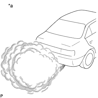
Text in Illustration *a Example
-
Start the engine.
-
Fully depress the accelerator pedal, and then release it.
-
Check whether white smoke is emitted or not when racing the engine.
Note
Be sure not to check for white smoke indoors.
Tech Tips
-
If the white smoke is emitted only just after engine start and disappears later, the smoke is not from the turbocharger.
-
If the turbocharger is the cause of the problem, regardless of whether the engine is cold or warmed up, there will be a large amount of white smoke to the extent that visibility is obstructed for a few meters in the area of the smoke (as shown in the illustration).
-
Depending on whether there is oil mixed with the fuel, or whether there is unburned fuel present, the smell of the exhaust gas differs. When oil is mixed in, the exhaust gas smells like burning oil.
-
When continuously traveling with the engine close to idle for 1 hour or more, such as when in heavy traffic, unburned fuel accumulates in the catalytic converter, and can produce white smoke when accelerating.
Result Result Proceed to White smoke is emitted just after engine start only A White smoke is always and continuously emitted B There is oil on the exhaust pipe, etc.*1 C Tech Tips
-
*1: The oil on the exhaust pipe may be from the transmission, etc.
-
White smoke may be emitted at a specific exhaust gas temperature. Listed are possible symptoms and causes for this case. Please use this information as reference when carrying out malfunction diagnosis.
-
The exhaust gas temperature may be checked using "Exhaust Temperature B1S2, Exhaust Temperature B1S3" in the Data List.
Symptoms Causes White smoke is emitted when the exhaust temperature is below 200°C (452°F) and the vehicle is traveling at low speed or when accelerating after decelerating.
-
Related Data List
- Exhaust Temperature B1S2
- Exhaust Temperature B1S3
When continuously traveling with the engine close to idle for 1 hour or more, such as when in heavy traffic, unburned fuel accumulates in the catalytic converter, and can produce white smoke when accelerating.*2
*2: In this case the white smoke is not caused by a defect, so explain to the customer that the white smoke is caused by an accumulation of unburned fuel due to low-speed driving etc., and monitor the situation.
(If the customer reports that the problem only occurs after continuous driving in heavy traffic/low speed driving, the problem may resolve itself when the catalytic converter temperature is raised through high-speed driving. However, if the catalytic converter activity is reduced, this will not resolve the problem, so the catalytic converter must be replaced. Deterioration of the catalytic converter can cause EGR malfunction and injector malfunction, so if there has not been any repair in the past, check and repair these components as well.)
White smoke is emitted when accelerating while the exhaust gas temperature is around 200 to 300°C (452 to 572°F) (in the process of rising to 500°C (932°F) for PM forced regeneration).
-
Related Data List
- DPNR/DPF Status Reju (PM)
- Exhaust Temperature B1S2
- Exhaust Temperature B1S3
-
Deterioration of the exhaust gas temperature sensor may be causing the sensor to read lower than the actual temperature, so the amount of fuel added is increased and white smoke is produced. In this case the sensor will need to be replaced.
-
If catalytic converter activity has decreased, more fuel will be added without an increase in exhaust gas temperature, possibly resulting in white smoke.
In this case the catalytic converter needs to be replaced. Deterioration of the catalytic converter can cause EGR and injector malfunction, so if there has not been any repair in the past, check these components as well and repair if necessary.
-
B 
CHECK IDLING CONDITION Click here
C
CHECK FOR OIL LEAKAGE Click here
A
-
-
CHECK TEMPERATURE WHEN WHITE SMOKE IS EMITTED
-
Check whether the white smoke is emitted only when the engine coolant temperature is below 0°C (32°F).
Tech Tips
-
If so, the smoke is not from the turbocharger and may be the smoke of unburned fuel.
-
If misfiring occurs, unburned fuel is emitted.
Result Result Proceed to White smoke is emitted when the temperature is below 0°C (32°F) A White smoke is emitted regardless of temperature B -
B
READ VALUE USING INTELLIGENT TESTER Click here
A
-
-
INSPECT GLOW PLUG (RESISTANCE)
-
Inspect the glow plug Click here.
NG
REPLACE GLOW PLUG Click here
OK
-
-
READ VALUE USING INTELLIGENT TESTER
-
Connect the intelligent tester to the DLC3.
-
Turn the ignition switch to ON and turn the tester on.
-
Start the engine
-
Enter the following menus: Powertrain / Engine and ECT / Data List / Fuel Press, Target Common Rail Pressure.
-
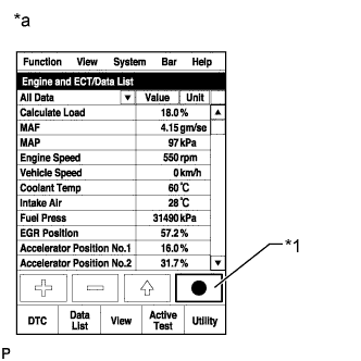
Text in Illustration *1 Snapshot Button *a Reference Take a snapshot with the intelligent tester.
Tech Tips
Detailed graphs can be displayed by transferring the stored snapshot from the tester to a PC (personal computer) with Intelligent Viewer installed.
-
Measure the difference between the target fuel pressure (Target Common Rail Pressure) and the actual fuel pressure (Fuel Press) when racing the engine with the accelerator pedal fully depressed.
Result Result Proceed to Fuel pressure is within 5000 kPa (51.0 kgf/cm2, 725 psi) of Target Common Rail Pressure
A Except above B Tech Tips
-
"Target Common Rail Pressure" is the target fuel pressure controlled by the ECM.
-
"Fuel Press" is the actual fuel pressure.
-
B
CHECK IF FUEL IS BEING SUPPLIED TO FUEL SUPPLY PUMP ASSEMBLY Click here
A
-
-
CHECK INJECTOR COMPENSATION CODE
-
Read the injector compensation codes Click here.
OK Compensation codes stored in the ECM match the compensation codes of the installed injector assemblies.
NG
REGISTER INJECTOR COMPENSATION CODE AND PERFORM PILOT QUANTITY LEARNING
OK
-
-
READ VALUE USING INTELLIGENT TESTER (INJECTION FEEDBACK VAL #1 TO #4, INJECTION VOLUME)
-
Check Injection Feedback Val #1 to #4 and Injection Volume in the snapshot taken after the engine is warmed up and idled for 1 minute with the A/C off.
Tech Tips
Engine coolant temperature is 70°C (158°F) or higher.
Result Result Proceed to Except below A Injection Feedback Val #1 to #4 are 3 mm3/st or less and Injection Volume is 4.5 to 10 mm3/st
B
B
PERFORM ACTIVE TEST USING INTELLIGENT TESTER (ACTIVATE THE EGR VALVE CLOSE) Click here
A
-
-
PERFORM ACTIVE TEST USING INTELLIGENT TESTER (CONTROL THE CYLINDER #1 TO #4 FUEL CUT)
Tech Tips
Use this Active Test to determine the malfunctioning cylinder.
-
Connect the intelligent tester to the DLC3.
-
Start the engine and turn the tester on.
-
Enter the following menus: Powertrain / Engine and ECT / Active Test / Control the Cylinder #1 to #4 Fuel Cut.
Tech Tips
If the engine idle speed does not change when an injector assembly is disabled, the cylinder being tested is malfunctioning. Record any malfunctioning cylinders.
NEXT
-
-
PERFORM ACTIVE TEST USING INTELLIGENT TESTER (CHECK THE CYLINDER COMPRESSION)
Tech Tips
Use this Active Test to help determine whether a cylinder has compression loss or not.
-
Connect the intelligent tester to the DLC3.
-
Turn the ignition switch to ON and turn the tester on.
-
Enter the following menus: Powertrain / Engine and ECT / Active Test / Check the Cylinder Compression / Data List / Compression / Engine Speed of Cyl #1 to #4.
-
Crank the engine.
-
Check the engine speed during the Active Test.
Result Result Proceed to Except below A The values of Engine Speed Cyl #1 to #4 are within 10 rpm of each other B Tech Tips
When cranking, if the speed of a cylinder is approximately 100 rpm more than the other cylinders, there is probably a complete loss of compression in that cylinder.
B
REPLACE INJECTOR ASSEMBLY OF MALFUNCTIONING CYLINDER Click here
A
-
-
CHECK CYLINDER COMPRESSION PRESSURE OF MALFUNCTIONING CYLINDER
Tech Tips
Measure the compression of the cylinder that had a high speed during the "Control the All Cylinders Fuel Cut" Active Test.
-
Check cylinder compression pressure Click here.
NG
CHECK ENGINE TO DETERMINE CAUSE OF LOW COMPRESSION
OK
-
-
REPLACE INJECTOR ASSEMBLY OF MALFUNCTIONING CYLINDER
Tech Tips
It can be determined that the injector assembly is faulty as the corresponding cylinder is malfunctioning, but has no compression loss.
-
Replace the injector assembly of the malfunctioning cylinder Click here.
Note
-
When replacing the injector assembly for a cylinder, always be sure to use a new injection pipe.
-
Follow the procedure in the repair manual and temporarily install the injection pipes and nozzle leakage pipe, and then correctly position the injector assemblies. After that, tighten parts according to the torque specifications.
-
If the installation procedure is not performed correctly, injector assemblies may become out of position, which may cause the injector assemblies to deteriorate, resulting in malfunctions.
-
If an injector assembly deteriorates and malfunctions, other problems such as knocking, rough idle, etc. may occur.
-
If an injector assembly becomes out of position, it is possible that the seal between the injector assembly and injection pipe may become incomplete, resulting in a fuel leak.
-
NEXT
-
-
BLEED AIR FROM FUEL SYSTEM
-
Bleed the air from the fuel system Click here.
NEXT
-
-
REGISTER INJECTOR COMPENSATION CODE AND PERFORM PILOT QUANTITY LEARNING
-
Register the injector compensation codes Click here.
-
Perform the injector pilot quantity learning Click here.
NEXT
-
-
CONFIRM WHETHER MALFUNCTION HAS BEEN SUCCESSFULLY REPAIRED
-
Check whether the white smoke problem has been successfully repaired by starting the engine.
NG
CHECK FUEL QUALITY Click here
OK 
END
-
-
CHECK FUEL QUALITY
-
Check that only diesel fuel is being used.
-
Check that the fuel does not contain any impurities.
NEXT
END
-
-
CHECK IF FUEL IS BEING SUPPLIED TO FUEL SUPPLY PUMP ASSEMBLY
-
Disconnect the inlet hose from the fuel supply pump assembly.
-
Operate the priming pump and check that fuel is being supplied to the fuel supply pump assembly.
OK Fuel is properly supplied to the fuel supply pump assembly when the priming pump is operated. Tech Tips
-
A lack of fuel causes the fuel pressure to drop.
-
Check that the fuel filter element sub-assembly is not clogged.
-
NEXT
-
-
CLEAN FUEL FILTER CASE AND REPLACE FUEL FILTER ELEMENT SUB-ASSEMBLY
-
Clean the fuel filter case and replace the fuel filter element sub-assembly.
Tech Tips
Be sure to clean the inside of the fuel filter case as the injector assemblies may not operate properly if the fuel filter element sub-assembly is installed with foreign matter remaining inside the fuel filter case.
NEXT
-
-
CHECK AND REPLACE CLOGGED FUEL PIPE (INCLUDING FROZEN FUEL) (FUEL TANK - FUEL SUPPLY PUMP ASSEMBLY)
-
Check and replace the clogged fuel pipe.
NEXT
-
-
BLEED AIR FROM FUEL SYSTEM
Tech Tips
If the fuel filter element sub-assembly or fuel pipe has been replaced, be sure to remove any air in the system.
-
Bleed the air from the fuel system Click here.
NEXT
-
-
CONFIRM WHETHER MALFUNCTION HAS BEEN SUCCESSFULLY REPAIRED
-
Check whether the white smoke problem has been successfully repaired by starting the engine.
NEXT
END
-
-
PERFORM ACTIVE TEST USING INTELLIGENT TESTER (ACTIVATE THE EGR VALVE CLOSE)
-
Connect the intelligent tester to the DLC3.
-
Start the engine and warm it up, and make sure the A/C switch and all accessory switches are off.
-
Turn the ignition switch off. Wait for 30 seconds, and then restart the engine.
-
Turn the tester on.
-
Enter the following menus: Powertrain / Engine and ECT / Data List / MAF.
-
Read the MAF value displayed on the tester while the engine is idling.
-
Enter the following menus: Powertrain / Engine and ECT / Active Test / Activate the EGR Valve Close.
-
Read the MAF value when the EGR valve is closed using the Active Test function.
Tech Tips
-
If idling continues for 20 minutes or more, the EGR valve target opening angle becomes 0% (EGR valve fully closed). As this makes diagnosis impossible, it becomes necessary to drive the vehicle or restart the engine.
-
Before performing the diagnosis, confirm that the EGR valve target opening angle is not 0%.
Result Active Test Result Proceed to Activate the EGR Valve Close:
Off (Open) to On (Closed)
MAF value does not change A MAF value changes B Note
As the measured values may differ from those shown below due to factors such as differences in measuring environments and changes in vehicle condition due to aging, do not use these values to determine whether the vehicle is malfunctioning or not.
Tech Tips
The problem may be a temporary one, due to the entry of deposits or foreign matter. Check that there are no deposits or foreign matter in the electric EGR control valve assembly or mass air flow meter.
Reference EGR Valve Condition (Opening) Measuring Condition MAF (Reference) Open (70%)
-
Atmosphere pressure: 101 kPa (757.5 mmHg, 29.8 in.Hg)
-
Intake air temperature: 30°C (86°F)
-
Engine coolant temperature: 88°C (190°F)
3 to 40 gm/sec Closed (0%) 38 to 52 gm/sec -
B
REMOVE DEPOSIT (ELECTRIC EGR CONTROL VALVE ASSEMBLY)
A
-
-
CHECK ENGINE ASSEMBLY
-
Inspect the engine to see whether white smoke is being emitted due to defects in the engine itself.
-
Check for oil leaking into the combustion chamber due to a faulty valve stem oil seal.
-
Check for oil leaking into the combustion chamber due to a faulty injector assembly nozzle sheet.
-
Check for low compression.
Tech Tips
If the engine runs too rough, Injection Feedback Val #1 to #4 cannot be corrected and the readout will (incorrectly) show that Injection Feedback Val #1 to #4 are within the normal range.
Tech Tips
If defects are found, perform repairs, and then check that the symptoms are no longer present.
-
NEXT
END
-
-
CHECK IDLING CONDITION
-
Start the engine.
-
Check the idling condition.
Result Result Proceed to Engine run smoothly at idle, however white smoke is emitted. A There are problems such as rough idling or engine stall, and white smoke is emitted.
Tech Tips
If the pressure in the crank case has risen, white smoke will be produced just after the engine is started. In this case, if blow-by gas is ejected when the oil level dipstick is slightly removed*, it is possible that the piston is damaged.
Note
*Do not completely remove the oil level dipstick as oil may spray from the opening.
B Tech Tips
It is possible to determine the faulty cylinder by carrying out the "Check the Cylinder Compression" Active Test.
B
REPAIR ENGINE ASSEMBLY
A
GO TO TURBOCHARGER OIL LEAK AND WHITE SMOKE Click here
-
-
CHECK FOR OIL LEAKAGE
-
Remove any oil in the front exhaust pipe assembly.
Tech Tips
Oil in the exhaust pipe is producing white smoke.
-
If there is an oil leak, repair the leak.
NEXT
END
-