ECD SYSTEM (w/ DPF) Starter Signal Circuit
DESCRIPTION
While the engine is being cranked, current flows from terminal ST1 of the ignition switch to the ST fuse and also flows to terminal STA of the ECM (STA Signal).
WIRING DIAGRAM
Refer to DTC P0617 Click here.
INSPECTION PROCEDURE
Note
-
Inspect the fuses of circuits related to this system before performing the following inspection procedure.
-
After replacing the ECM, the new ECM needs registration Click here and initialization Click here.
-
After replacing the fuel supply pump assembly or suction control valve, the ECM needs initialization Click here.
-
After replacing an injector assembly, the ECM needs registration Click here.
Tech Tips
This chart is based on the premise that the engine can crank normally. If the engine cannot crank normally, proceed to Problem Symptoms Table Click here.
PROCEDURE
-
CHECK WHETHER ENGINE CAN BE CRANKED
-
Check if the engine can be cranked.
Result Result Proceed to Engine can be cranked A Engine cannot be cranked B
B 
READ VALUE USING INTELLIGENT TESTER (STARTER SIGNAL) Click here
A 
-
-
READ VALUE USING INTELLIGENT TESTER (STARTER SIGNAL)
-
Connect the intelligent tester to the DLC3.
-
Turn the ignition switch to ON and turn the tester on.
-
Enter the following menus: Powertrain / Engine and ECT / Data List / Starter Signal.
-
Check the value displayed on the tester when the ignition switch is turned to the ON and START positions.
OK Ignition Switch Condition Starter Signal ON OFF START ON
NG
CHECK HARNESS AND CONNECTOR (IGNITION SWITCH ASSEMBLY - ECM - STARTER RELAY HOLDER) Click here
OK 
PROCEED TO NEXT SUSPECTED AREA SHOWN IN PROBLEM SYMPTOMS TABLE Click here
-
-
CHECK HARNESS AND CONNECTOR (IGNITION SWITCH ASSEMBLY - ECM - STARTER RELAY HOLDER)
-
Disconnect the ECM connector.
-
Disconnect the ignition switch assembly connector.
-
Remove the STARTER relay from the engine room relay block.
-
Measure the resistance according to the value(s) in the table below.
Standard Resistance Tester Connection Condition Specified Condition E17-6 (STA) - I15-3 (ST1) Always Below 1 Ω E17-6 (STA) or I15-3 (ST1) or STARTER relay holder 1 - Body ground Always 10 kΩ or higher
NG 
REPAIR OR REPLACE HARNESS OR CONNECTOR
OK
PROCEED TO NEXT SUSPECTED AREA SHOWN IN PROBLEM SYMPTOMS TABLE Click here
-
-
READ VALUE USING INTELLIGENT TESTER (STARTER SIGNAL)
-
Connect the intelligent tester to the DLC3.
-
Turn the ignition switch to ON.
-
Turn the tester on.
-
Enter the following menus: Powertrain / Engine and ECT / Data List / Starter Signal.
-
Check the value displayed on the tester when the ignition switch is turned to the ON and START positions.
OK Ignition Switch Condition Starter Signal ON OFF START ON
NG
CHECK WHETHER ENGINE CAN BE CRANKED Click here
OK
-
-
INSPECT STARTER RELAY
-
Inspect the STARTER relay Click here.
NG
REPLACE STARTER RELAY
OK
-
-
CHECK HARNESS AND CONNECTOR (IGNITION SWITCH ASSEMBLY - STARTER RELAY HOLDER, STARTER RELAY HOLDER - BODY GROUND)
-
Disconnect the ignition switch assembly connector.
-
Remove the STARTER relay from the engine room relay block.
-
Measure the resistance according to the value(s) in the table below.
Standard Resistance Tester Connection Condition Specified Condition I15-3 (ST1) - STARTER relay holder 1 Always Below 1 Ω STARTER relay holder 2 - Body ground Always Below 1 Ω I15-3 (ST1) or STARTER relay holder 1 - Body ground Always 10 kΩ or higher
NG
REPAIR OR REPLACE HARNESS OR CONNECTOR
OK
-
-
CHECK TERMINAL VOLTAGE (STARTER RELAY VOLTAGE)
-
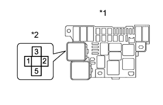
Text in Illustration *1 Engine Room Relay Block *2 STARTER Relay Holder Remove the STARTER relay from the engine room relay block.
-
Measure the voltage according to the value(s) in the table below.
Standard Voltage Tester Connection Condition Specified Condition STARTER relay holder 5 - Body ground Always 11 to 14 V
NG
REPAIR OR REPLACE HARNESS OR CONNECTOR (BATTERY - STARTER RELAY HOLDER)
OK
PROCEED TO NEXT SUSPECTED AREA SHOWN IN PROBLEM SYMPTOMS TABLE Click here
-
-
CHECK WHETHER ENGINE CAN BE CRANKED
-
Disconnect the ECM connector
-
Check if the engine can be cranked.
Result Result Proceed to Engine cannot be cranked A Engine can be cranked B
B
CHECK HARNESS AND CONNECTOR (ECM - IGNITION SWITCH ASSEMBLY - STARTER RELAY) Click here
A
-
-
INSPECT STARTER RELAY
-
Inspect the STARTER relay Click here.
NG
REPLACE STARTER RELAY
OK
-
-
CHECK HARNESS AND CONNECTOR (IGNITION SWITCH ASSEMBLY - ECM - STARTER RELAY HOLDER)
-
Disconnect the ECM connector.
-
Disconnect the ignition switch assembly connector.
-
Remove the STARTER relay from the engine room relay block.
-
Measure the resistance according to the value(s) in the table below.
Standard Resistance Tester Connection Condition Specified Condition E17-6 (STA) - I15-3 (ST1) Always Below 1 Ω E17-6 (STA) - STARTER relay holder 1 Always Below 1 Ω E17-6 (STA) or I15-3 (ST1) or STARTER relay holder 1 - Body ground Always 10 kΩ or higher
NG
REPAIR OR REPLACE HARNESS OR CONNECTOR
OK
-
-
INSPECT IGNITION SWITCH ASSEMBLY
-
Inspect the ignition switch assembly Click here.
NG
REPLACE IGNITION SWITCH ASSEMBLY Click here
OK
-
-
CHECK TERMINAL VOLTAGE (IGNITION SWITCH VOLTAGE)
-
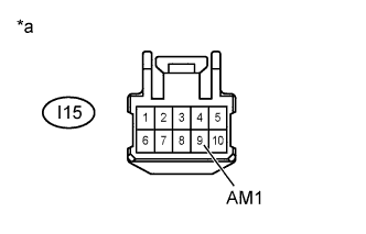
Text in Illustration *a Front view of wire harness connector
(to Ignition Switch Assembly)
Disconnect the ignition switch assembly connector.
-
Measure the voltage according to the value(s) in the table below.
Standard Voltage Tester Connection Condition Specified Condition I15-9 (AM1) - Body ground Always 11 to 14 V
NG
REPAIR OR REPLACE HARNESS OR CONNECTOR (IGNITION SWITCH ASSEMBLY - BATTERY)
OK
PROCEED TO NEXT SUSPECTED AREA SHOWN IN PROBLEM SYMPTOMS TABLE Click here
-
-
CHECK HARNESS AND CONNECTOR (ECM - IGNITION SWITCH ASSEMBLY - STARTER RELAY)
-
Disconnect the ECM connector.
-
Disconnect the ignition switch assembly connector.
-
Remove the STARTER relay from the engine room relay block.
-
Measure the resistance according to the value(s) in the table below.
Standard Resistance Tester Connection Condition Specified Condition E17-6 (STA) - I15-3 (ST1) Always Below 1 Ω E17-6 (STA) - STARTER relay holder 1 Always Below 1 Ω E17-6 (STA) or I15-3 (ST1) or STARTER relay holder 1 - Body ground Always 10 kΩ or higher
NG
REPAIR OR REPLACE HARNESS OR CONNECTOR
OK
REPLACE ECM Click here
-