ECD SYSTEM, Diagnostic DTC:P0400
| DTC Code | DTC Name |
|---|---|
| P0400 | Exhaust Gas Recirculation Flow |
DESCRIPTION
The EGR system recirculates exhaust gases, and is controlled to the proper volume to be suitable for all driving conditions. The recirculated gas mixes with the intake air, allowing the EGR system to slow down engine combustion and lower the combustion temperature. This helps reduce NOx emissions.
In order to increase circulation efficiency, the ECM adjusts the lift amount of the EGR valve and throttle valve.
| DTC No. | DTC Detection Condition | Trouble Area |
|---|---|---|
| P0400 | When either condition below is met:
|
|
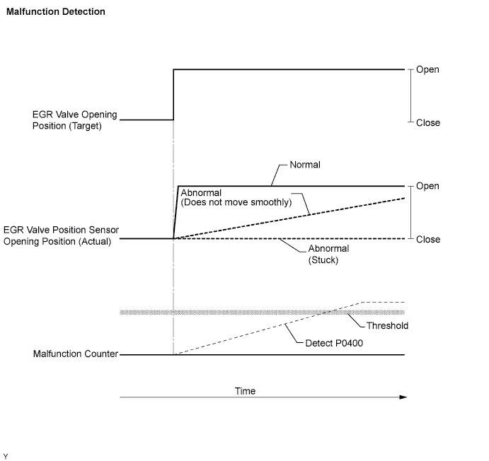
MONITOR DESCRIPTION
-
If the electric EGR control valve is forcibly operated but the intake air amount does not vary, the ECM determines that the electric EGR control valve is malfunctioning. The ECM then illuminates the MIL.
-
When the target and actual positions of the electric EGR control valve are different, the ECM interprets this as a malfunction of the electric EGR control valve and illuminates the MIL.
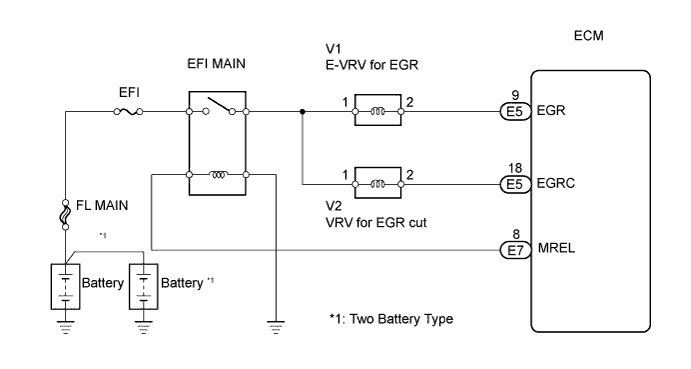
WIRING DIAGRAM
INSPECTION PROCEDURE
Note
After replacing the ECM, the new ECM needs registration Click here and initialization Click here.
Tech Tips
-
Read freeze frame data using the intelligent tester. The ECM records vehicle and driving condition information as freeze frame data the moment a DTC is stored. When troubleshooting, freeze frame data can help determine if the vehicle was running or stopped, if the engine was warmed up or not, and other data from the time the malfunction occurred.
-
After warming up the engine, DTC P0400 can be set if 1 second or more passes after quickly accelerating the engine from idling.
PROCEDURE
-
CHECK ANY OTHER DTCS OUTPUT (IN ADDITION TO DTC P0400)
-
Connect the intelligent tester to the DLC3.
-
Turn the ignition switch ON and turn the tester ON.
-
Select the following menu items: Powertrain / Engine and ECT / DTC.
-
Read DTCs.
Result Display (DTC Output) Proceed to P0400 A P0400 and P0405 and/or P0406 B Tech Tips
If codes other than P0400 are output, perform troubleshooting for those DTCs first.
B 
GO TO DTC CHART
A 
-
-
CHECK VACUUM PUMP ASSEMBLY
-
Check the negative pressure of the vacuum pump Click here.
Standard More than 86.7 kPa (650 mmHg, 26 in.Hg)
NG
REPLACE VACUUM PUMP ASSEMBLY
OK
-
-
CHECK VACUUM HOSES
-
Check the vacuum hoses.
OK The hoses are not damaged and securely connected.
NG
REPAIR OR REPLACE VACUUM HOSE
OK
-
-
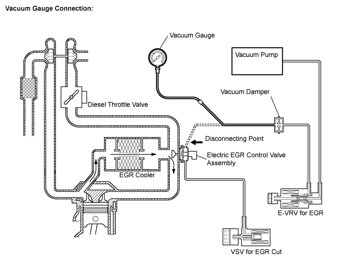
PERFORM ACTIVE TEST USING INTELLIGENT TESTER (CONTROL THE EGR SYSTEM)
-
Disconnect the vacuum hose to the electric EGR control valve.
-
Connect the vacuum gauge to the E-VRV side vacuum hose.
-
Connect an intelligent tester to the DLC3.
-
Start the engine and turn the tester ON.
-
Warm up the engine until the engine coolant temperature reaches 80°C (176°F).
-
Select the following menu items: Powertrain / Engine / Active Test / Control the EGR System.
-
Check the pressure variation when the E-VRV for EGR is turned from OFF to ON using the Active Test function.
-
Disconnect the vacuum gauge.
-
Reconnect the vacuum hose to the electric EGR control valve.
B 
INSPECT ELECTRIC EGR CONTROL VALVE ASSEMBLY (E-VRV FOR EGR) Click here
A
-
-
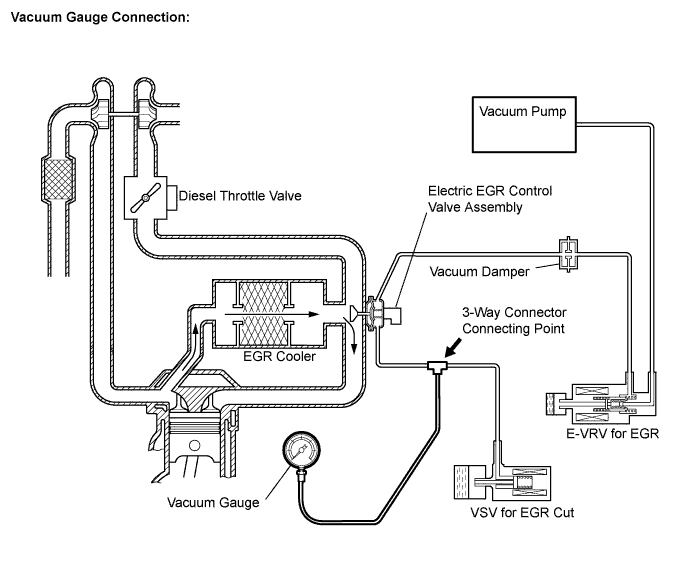
PERFORM ACTIVE TEST USING INTELLIGENT TESTER (ACTIVATE THE VSV FOR EGR CUT)
-
Using a 3-way connector, connect a vacuum gauge to the hose between the VSV for EGR cut and electric EGR control valve assembly.
-
Connect an intelligent tester to the DLC3.
-
Start the engine and turn the tester ON.
-
Select the following menu items: Powertrain / Engine / Active Test / Activate the VSV for EGR Cut.
-
Check the pressure variation when the E-VRV for EGR is turned from OFF to ON using the Active Test function.
Result Active Test Vacuum Gauge Proceed To OFF to ON Pressure rises from above 28 kPa (210 mmHg, 8.3 in.Hg) to 0 kPa (0 mmHg, 0 in.Hg) A Pressure fixed at 0kPa (0 mmHg, 0 in.Hg), or above 28kPa (210 mmHg, 8.3 in.Hg) B
B
INSPECT VACUUM SWITCHING VALVE (VSV FOR EGR CUT) Click here
A
-
-
INSPECT ELECTRIC EGR CONTROL VALVE ASSEMBLY (EGR VALVE OPERATION)
-
Inspect the electric EGR control valve assembly Click here.
OK The valve is not stuck and does not have heavy carbon deposits
NG
REPLACE ELECTRIC EGR CONTROL VALVE ASSEMBLY
OK 
REPLACE ECM
-
-
INSPECT ELECTRIC EGR CONTROL VALVE ASSEMBLY (E-VRV FOR EGR)
-
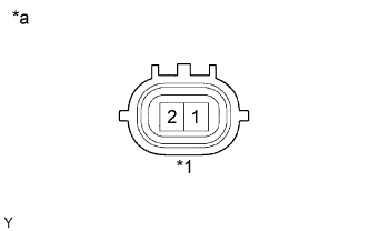
Text in Illustration *1 E-VRV Connector *a Component Side Disconnect the V1 E-VRV for EGR connector.
-
Measure the resistance of the E-VRV for EGR.
Standard resistance Tester Connection Condition Specified Condition 1 - 2 20°C (68°F) 11 to 13 Ω -
Reconnect the E-VRV for EGR connector.
NG
REPLACE ELECTRIC EGR CONTROL VALVE ASSEMBLY
OK
-
-
CHECK HARNESS AND CONNECTOR (E-VRV FOR EGR - ECM)
-
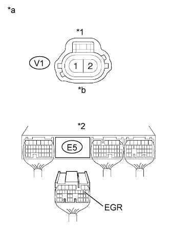
Text in Illustration *1 E-VRV for EGR Connector *2 ECM Connector *a Wire Harness Side *b Front View Disconnect the V1 E-VRV for EGR connector.
-
Disconnect the E5 ECM connector.
-
Check the resistance.
Standard resistance (Check for open) Tester Connection Specified Condition V1-2 - E5-9 (EGR) Below 1 Ω Standard resistance (Check for short) Tester Connection Specified Condition V1-2 or E5-9 (EGR) - Body ground 10 kΩ or higher -
Reconnect the E-VRV for EGR connector.
-
Reconnect the ECM connector.
NG
REPAIR OR REPLACE HARNESS AND CONNECTOR
OK
-
-
CHECK HARNESS AND CONNECTOR (E-VRV FOR EGR - EFI MAIN RELAY)
-
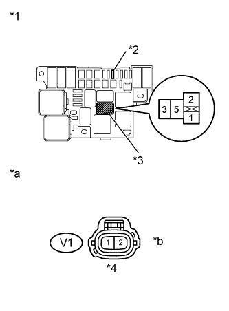
Text in Illustration *1 R/B No.2 *2 EFI Fuse *3 EFI MAIN relay *4 E-VRV for EGR Connector *a Wire Harness Side *b Front View Inspect the EFI fuse.
-
Remove the EFI fuse from the R/B No. 2.
-
Check the EFI fuse resistance.
Standard resistance Below 1 Ω -
Reinstall the EFI fuse.
-
-
Check the wire harness between the E-VRV for EGR and EFI MAIN relay.
-
Disconnect the V1 E-VRV for EGR connector.
-
Remove the EFI MAIN relay from the R/B No. 2.
-
Check the resistance.
Standard resistance (Check for open) Tester Connection Specified Condition R/B No. 2 (EFI MAIN relay terminal 3) - V1-1 Below 1 Ω Standard resistance (Check for short) Tester Connection Specified Condition R/B No. 2 (EFI MAIN relay terminal 3) or V1-1 - Body ground 10 kΩ or higher -
Reconnect the E-VRV for EGR connector.
-
Reinstall the EFI MAIN relay.
-
NG
REPAIR OR REPLACE HARNESS AND CONNECTOR
OK
REPLACE ECM
-
-
INSPECT VACUUM SWITCHING VALVE (VSV FOR EGR CUT)
-
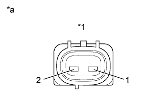
Text in Illustration *1 VSV for EGR Cut *a Component Side Disconnect the V2 VSV for EGR cut connector.
-
Measure the resistance of the VSV for EGR cut.
Standard resistance Tester Connection Specified Condition 1 - 2 37 to 44 Ω at 20°C (68°F) -
Reconnect the VSV for EGR cut connector.
NG
REPLACE VACUUM SWITCHING VALVE ASSEMBLY NO.1
OK
-
-
CHECK HARNESS AND CONNECTOR (VSV FOR EGR CUT - ECM)
-
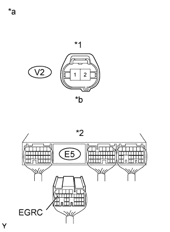
Text in Illustration *1 VSV for EGR Cut Connector *2 ECM Connector *a Wire Harness Side *b Front View Disconnect the V2 VSV for EGR cut connector.
-
Disconnect the E5 ECM connector.
-
Check the resistance.
Standard resistance (Check for open) Tester Connection Specified Condition E5-18 (EGRC) - V2-2 Below 1 Ω Standard resistance (Check for short) Tester Connection Specified Condition E5-18 (EGRC) or V2-2 - Body ground 10 kΩ or higher -
Reconnect the ECM connector.
-
Reconnect the VSV for EGR cut connector.
NG
REPAIR OR REPLACE HARNESS AND CONNECTOR
OK
-
-
CHECK HARNESS AND CONNECTOR (VSV FOR EGR CUT - MAIN RELAY)
-
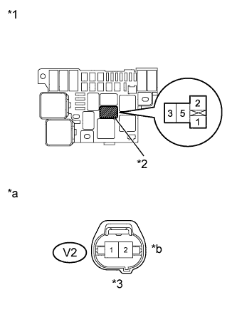
Text in Illustration *1 R/B No.2 *2 EFI MAIN Relay *3 VSV for EGR Cut Connector *a Wire Harness Side *b Front View Remove the EFI MAIN relay from the R/B No. 2.
-
Disconnect the V2 VSV for EGR cut connector.
-
Check the resistance.
Standard resistance (Check for open) Tester Connection Specified Condition R/B No. 2 (EFI MAIN relay terminal 3) - V2-1 Below 1 Ω Standard resistance (Check for short) Tester Connection Specified Condition R/B No. 2 (EFI MAIN relay terminal 3) or V2-1 - Body ground 10 kΩ or higher -
Reinstall the EFI MAIN relay.
-
Reconnect the VSV for EGR cut connector.
NG
REPAIR OR REPLACE HARNESS AND CONNECTOR
OK
REPLACE ECM
-