ECD SYSTEM, Diagnostic DTC:P0340
| DTC Code | DTC Name |
|---|---|
| P0340 | Camshaft Position Sensor "A" Circuit (Bank 1 or Single Sensor) |
DESCRIPTION
The camshaft position sensor (G signal) consists of a magnet, iron core and pickup coil.
The G signal plate has 5 teeth on its outer circumference and is installed in the pump drive shaft pulley. When the pump drive shaft pulley rotates, the protrusion on the signal plate and the air gap on the pickup coil change, causing fluctuations in the magnetic field and generating an electromotive force in the pickup coil.
The NE signal plate has 34 teeth and is mounted on the crank angle sensor plate. The NE signal sensor generates 34 signals at every engine revolution. The ECM detects the standard crankshaft angle based on the G signal and the actual crankshaft angle and the engine speed by the NE signal.
| DTC No. | DTC Detection Condition | Trouble Area |
|---|---|---|
| P0340 | When either condition below is met:
|
|
WIRING DIAGRAM
Refer to DTC P0335 Click here.
INSPECTION PROCEDURE
Tech Tips
Read freeze frame data using the intelligent tester. Freeze frame data records the engine conditions when a malfunction is detected. When troubleshooting, freeze frame data can help determine if the vehicle was running or stopped, if the engine was warmed up or not, and other data from the time the malfunction occurred.
Note
If the ECM is replaced, the new ECM needs initialization Click here.
PROCEDURE
-
INSPECT CAMSHAFT POSITION SENSOR (RESISTANCE)
-
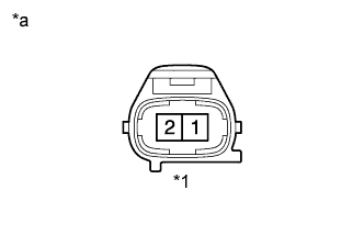
Text in Illustration *1 Camshaft Position Sensor *a Component Side Disconnect the C1 camshaft position sensor connector.
-
Measure the resistance between terminals 1 and 2.
Standard resistance Tester Connections Conditions Specified Conditions 1 - 2 Cold 835 to 1,400 Ω 1 - 2 Hot 1,060 to 1,645 Ω -
Reconnect the camshaft position sensor connector.
NG 
REPLACE CAMSHAFT POSITION SENSOR
OK 
-
-
CHECK HARNESS AND CONNECTOR (CAMSHAFT POSITION SENSOR - ECM)
-
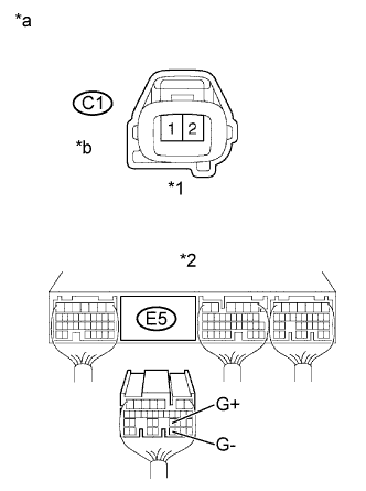
Text in Illustration *1 Camshaft Position Sensor Connector *2 ECM Connector *a Wire Harness Side *b Front View Disconnect the C1 camshaft position sensor connector.
-
Disconnect the E5 ECM connector.
-
Check the resistance.
Standard resistance (Check for open) Tester Connections Specified Conditions C1-1 - E5-23 (G+) Below 1 Ω C1-2 - 5-31 (G-) Below 1 Ω Standard resistance (Check for short) Tester Connections Specified Conditions C1-1 or E5-23 (G+) - Body ground 10 kΩor higher C1-2 or 5-31 (G-) - Body ground 10 kΩor higher -
Reconnect the ECM connector.
-
Reconnect the camshaft position sensor connector.
NG
REPAIR OR REPLACE HARNESS OR CONNECTOR
OK
-
-
CHECK SENSOR INSTALLATION (CAMSHAFT POSITION SENSOR)
-
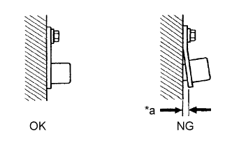
Text in Illustration *a Clearance Check the camshaft position sensor installation.
OK Camshaft position sensor is installed correctly.
NG
SECURELY REINSTALL CAMSHAFT POSITION SENSOR
OK
-
-
CHECK PUMP DRIVE SHAFT PULLEY
-
Check the teeth of the pump drive shaft pulley.
OK Pulley's teeth do not have any cracks or deformation.
NG
REPLACE PUMP DRIVE SHAFT PULLEY
OK 
REPLACE ECM
-