ECD SYSTEM, Diagnostic DTC:P0335, P0339
| DTC Code | DTC Name |
|---|---|
| P0335 | Crankshaft Position Sensor "A" Circuit |
| P0339 | Crankshaft Position Sensor "A" Circuit Intermittent |
DESCRIPTION
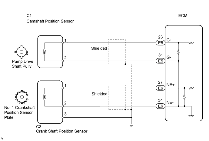
The crankshaft position sensor system consists of a crankshaft position sensor plate and a pickup coil.
The sensor plate has 34 teeth and is installed on the crankshaft. The pickup coil is made of an iron core and magnet. The crankshaft position sensor plate No. 1 rotates, and a pulse signal is created as each tooth passes by the pickup coil. The pickup coil generates 34 signals for each engine revolution. Based on these signals, the ECM calculates the crankshaft position and engine RPM. Using these calculations, the common rail injection system is controlled.
| DTC No. | DTC Detection Condition | Trouble Area |
|---|---|---|
| P0335 | When either condition below is met:
|
|
| P0339 |
|
|
WIRING DIAGRAM
INSPECTION PROCEDURE
Note
If the ECM is replaced, the new ECM needs initialization Click here.
Tech Tips
-
If no trouble is found in the diagnostic troubleshooting procedure of DTC P0335, troubleshoot the engine mechanical system.
-
Read freeze frame data using the intelligent tester. Freeze frame data records the engine conditions when a malfunction is detected. When troubleshooting, freeze frame data can help determine if the vehicle was running or stopped, if the engine was warmed up or not, and other data from the time the malfunction occurred.
PROCEDURE
-
INSPECT CRANKSHAFT POSITION SENSOR (RESISTANCE)
-
Disconnect the C3 crankshaft position sensor connector.
-
Measure the resistance of the sensor.
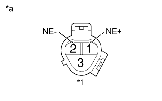
Standard resistance Tester Connection Condition Specified Condition 1 - 2 Cold 1,630 to 2,740 Ω 1 - 2 Hot 2,065 to 3,225 Ω Text in Illustration *1 Crankshaft Position Sensor *a Component Side Tech Tips
-
In the chart above, the terms "cold" and "hot" refer to the temperature of the sensor. "Cold" means approximately -10 to 50°C (14 to 122°F). "Hot" means approximately 50 to 100°C (122 to 212°F).
-
While cranking or idling the engine, check the waveform of the ECM connectors using an oscilloscope.
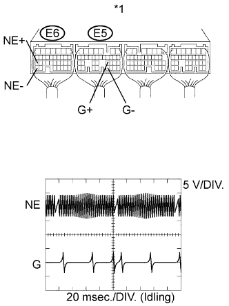
Reference Tester Connection Specified Condition E5-23 (G+) - E5-31 (G-)
E6-27 (NE+) - E6-34 (NE-)
Correct waveform is as shown Tool Setting Condition 5 V/DIV., 20 msec./DIV. Idling with warm engine Text in Illustration *1 ECM Connector Tech Tips
The waveform varies depending on the engine speed.
-
-
Reconnect the crankshaft position sensor connector.
NG 
REPLACE CRANKSHAFT POSITION SENSOR
OK 
-
-
CHECK HARNESS AND CONNECTOR (CRANKSHAFT POSITION SENSOR - ECM)
-
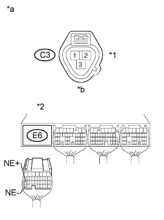
Text in Illustration *1 Crankshaft Position Sensor *2 ECM *a Wire Harness Side *b Front View Disconnect the C3 crankshaft position sensor connector.
-
Disconnect the E6 ECM connector.
-
Check the resistance.
Standard resistance (Check for open) Tester Connections Specified Conditions C3-1 - E6-27 (NE+) Below 1 Ω C3-2 - E6-34 (NE-) Below 1 Ω Standard resistance (Check for open) Tester Connections Specified Conditions C3-1 or E6-27 (NE+) - Body ground 10 kΩ or higher C3-2 or E6-34 (NE-) - Body ground 10 kΩ or higher -
Reconnect the ECM connector.
-
Reconnect the crankshaft position sensor connector.
NG
REPAIR OR REPLACE HARNESS OR CONNECTOR
OK
-
-
CHECK SENSOR INSTALLATION (CRANKSHAFT POSITION SENSOR)
-
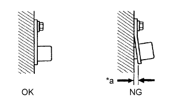
Text in Illustration *a Clearance Check the crankshaft position sensor installation.
OK Sensor is installed correctly.
NG
SECURELY REINSTALL CRANKSHAFT POSITION SENSOR
OK
-
-
CHECK CRANKSHAFT POSITION SENSOR PLATE NO.1
-
Check the teeth of the crankshaft position sensor plate No. 1.
OK Crankshaft position sensor plate No. 1 does not have any cracks or deformation.
NG
REPLACE CRANKSHAFT POSITION SENSOR PLATE NO.1
OK 
REPLACE ECM
-