ECD SYSTEM, Diagnostic DTC:P0095, P0097, P0098
| DTC Code | DTC Name |
|---|---|
| P0095 | Intake Air Temperature Sensor 2 Circuit |
| P0097 | Intake Air Temperature Sensor 2 Circuit Low |
| P0098 | Intake Air Temperature Sensor 2 Circuit High |
DESCRIPTION
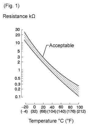
The diesel turbo Intake Air Temperature (IAT) sensor is built into the charge air cooler and senses the IAT. A built-in thermistor in the sensor changes its resistance value according to the intake air temperature. The lower the intake air temperature, the greater the thermistor resistance value. The higher the intake air temperature, the lower the thermistor resistance value (see Fig. 1).
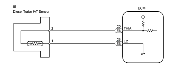
The sensor is connected to the ECM. The 5 V power source voltage in the ECM is applied to the sensor from terminal THIA via resistor R. Resistor R and the sensor are connected in series. When the resistance value of the sensor changes in accordance with changes in the IAT, the potential at terminal THIA also changes. Based on this signal, the ECM corrects the fuel injection volume to improve driveability with a cold engine.
| DTC No. | DTC Detection Condition | Trouble Area |
|---|---|---|
| P0095 | Open or short in diesel turbo IAT sensor circuit for 0.5 seconds (1 trip detection logic) |
|
| P0097 | Short in diesel turbo IAT sensor circuit for 0.5 seconds (sensor resistance value less than 25 Ω [sensor output voltage less than 0.05 V]) (1 trip detection logic) |
|
| P0098 | Open in diesel turbo IAT sensor circuit for 0.5 seconds (sensor resistance value more than 156 kΩ [sensor output voltage more than 4.9 V]) (1 trip detection logic) |
|
WIRING DIAGRAM
INSPECTION PROCEDURE
Tech Tips
-
If DTCs related to different systems that have terminal E2 as the ground terminal are output simultaneously, terminal E2 may have an open circuit.
-
Read freeze frame data using the intelligent tester. Freeze frame data records the engine conditions when a malfunction is detected. When troubleshooting, freeze frame data can help determine if the vehicle was running or stopped, if the engine was warmed up or not, and other data from the time the malfunction occurred.
Note
If the ECM is replaced, the new ECM needs initialization Click here.
PROCEDURE
-
INSPECT ECM (THIA VOLTAGE)
-
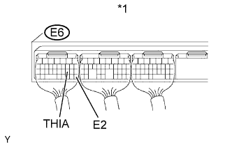
Text in Illustration *1 ECM Connector Turn the ignition switch ON.
-
Measure the voltage between the terminals of the E6 ECM connector.
Standard voltage Tester Connection Condition Specified Condition E6-20 (THIA) - E6-28 (E2) 20°C (68°F) 0.5 to 3.4 V
OK 
CHECK FOR INTERMITTENT PROBLEMS
NG 
-
-
INSPECT DIESEL TURBO INTAKE AIR TEMPERATURE SENSOR
-
Remove the diesel turbo IAT sensor.
-
Measure the diesel turbo IAT sensor resistance.
Standard resistance Tester Connection Condition Specified Condition 1 - 2 20°C (68°F) 2.21 to 2.65 kΩ Note
When checking the diesel turbo IAT sensor in water, do not allow water to come into contact with the terminals. After checking, dry the sensor.
-
Reinstall the diesel turbo IAT sensor.
NG
REPLACE DIESEL TURBO INTAKE AIR TEMPERATURE SENSOR
OK
-
-
CHECK HARNESS AND CONNECTOR (ECM - DIESEL TURBO INLET AIR TEMPERATURE SENSOR)
-
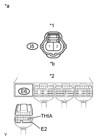
Text in Illustration *1 Diesel Turbo IAT Sensor Connector *2 ECM Connector *a Wire Harness Side *b Front View Disconnect the I5 diesel turbo IAT sensor connector.
-
Disconnect the E6 ECM connector.
-
Check the resistance.
Standard resistance (Check for open) Tester Connection Specified Condition I5-2 - E6-20 (THIA) Below 1 Ω I5-1 - E6-28 (E2) Below 1 Ω Standard resistance (Check for short) Tester Connection Specified Condition I5-2 or E6-20 (THIA) - Body ground 10 kΩ or higher -
Reconnect the diesel turbo IAT sensor connector.
-
Reconnect the ECM connector.
NG
REPAIR OR REPLACE HARNESS OR CONNECTOR
OK 
REPLACE ECM
-