ECD SYSTEM, Diagnostic DTC:P0046
| DTC Code | DTC Name |
|---|---|
| P0046 | Turbocharger / Supercharger Boost Control Solenoid Circuit Range / Performance |
DESCRIPTION
Variable nozzle vane type turbocharger consists primarily of a compressor wheel, turbine wheel, nozzle vane, unison ring, DC motor and nozzle vane position sensor.
The ECM outputs a signal to the turbo motor driver, which actuates the DC motor, to control the nozzle vane position.
| DTC No. | DTC Detection Condition | Trouble Area |
|---|---|---|
| P0046 | Either of following conditions met: Turbocharger variable Nozzle motor drive duty ratio +/- 100 % for 1.3 seconds or more Turbocharger variable Nozzle motor drive current 2.2 A or more for 5 seconds or more when motor driving (1 trip detection logic) |
|
WIRING DIAGRAM
INSPECTION PROCEDURE
Tech Tips
Read freeze frame data using the intelligent tester. Freeze frame data records the engine conditions when a malfunction is detected. When troubleshooting, freeze frame data can help determine if the vehicle was running or stopped, if the engine was warmed up or not, and other data from the time the malfunction occurred.
Note
If the ECM is replaced, the new ECM needs initialization Click here.
PROCEDURE
-
CHECK ANY OTHER DTCS OUTPUT (IN ADDITION TO P0046)
-
Connect the intelligent tester to the DLC3.
-
Turn the ignition switch ON and turn the tester ON.
-
Select the following menu items: Powertrain / Engine and ECT / DTC.
-
Read DTCs.
Result Display (DTC Output) Proceed to P0046 A P0046 and other DTCs B Tech Tips
If any DTCs other than P0046 are output, troubleshoot those DTCs first.
B 
GO TO DTC CHART Click here
A 
-
-
INSPECT TURBOCHARGER SUB-ASSEMBLY (DC MOTOR OPERATION)
-
Turn the ignition switch ON.
-
Turn the ignition switch OFF and check the DC motor operation.
OK When ignition switch is turned OFF, operation link moves as shown in A through D in illustration below. Operation link and motor rod move smoothly when moving from position shown in A to that shown in B, and from position shown in B to that shown in C. 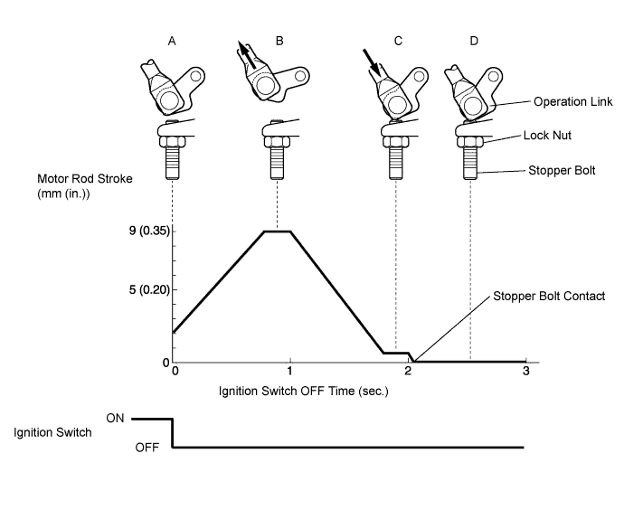
NG 
INSPECT TURBO MOTOR DRIVER Click here
OK 
CHECK FOR INTERMITTENT PROBLEMS Click here
-
-
INSPECT TURBO MOTOR DRIVER
-
Voltage Inspection
-
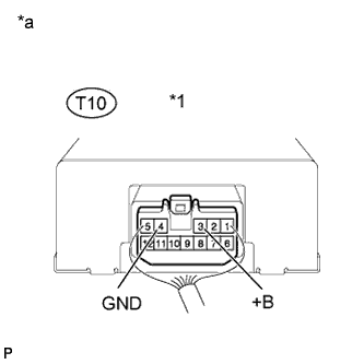
Text in Illustration *1 Turbo Motor Driver *a Component Side Turn the ignition switch ON (IG).
-
Measure the voltage between the terminals of the turbo motor driver connector.
Standard voltage Tester Connection Specified Condition +B (T10-3) - GND (T10-4) 11 to 14 V
-
-
Output Waveform Inspection
-
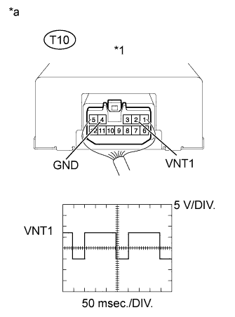
Text in Illustration *1 Turbo Motor Driver *a Component Side Turn the ignition switch ON (IG).
-
Check the waveform of the ECM connectors using an oscilloscope.
OK Tester Connection Condition Specified Condition VNT1 (T10-2) - GND (T10-4) Ignition switch ON Correct waveform is as shown
-
NG
REPLACE TURBO MOTOR DRIVER
OK
-
-
INSPECT TURBOCHARGER SUB-ASSEMBLY (DC MOTOR RESISTANCE)
-
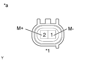
Text in Illustration *1 DC Motor *a Wire Harness Side Disconnect the T9 DC motor connector.
-
Measure the resistance between the terminals of the DC motor connector.
Standard resistance Tester Connection Specified Condition 1 (M+) - 2 (M-) 1 to 100 Ω -
Reconnect the DC motor connector.
NG
REPLACE TURBOCHARGER SUB-ASSEMBLY Click here
OK
-
-
CHECK HARNESS AND CONNECTOR (DC MOTOR - TURBO MOTOR DRIVER)
-
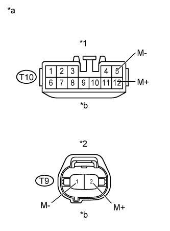
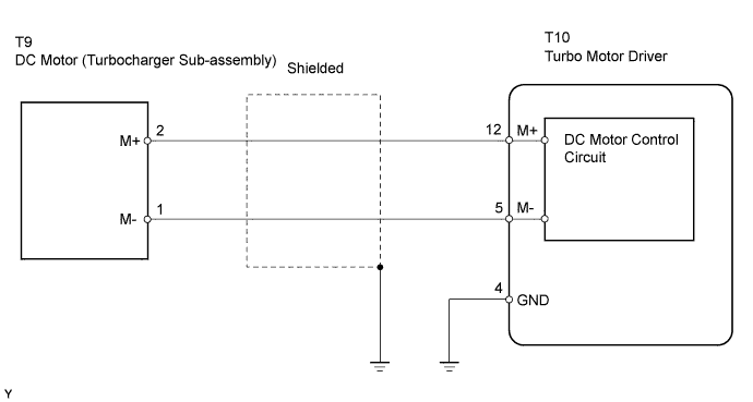
Text in Illustration *1 Turbo Motor Driver Connector *2 DC Motor Connector *a Wire Harness Side *b Front View Disconnect the T9 DC motor connector.
-
Disconnect the T10 turbo motor drive connector.
-
Check the resistance.
Standard resistance (Check for open) Tester Connections Specified Conditions T10-12 (M+) - T9-2 (M+) Below 1 Ω T10-5 (M-) - T9-1 (M-) Below 1 Ω Standard resistance (Check for short) Tester Connections Specified Conditions T10-12 (M+) or T9-2 (M+) - Body ground 10 kΩ or higher T10-5 (M-) or T9-1 (M-) - Body ground 10 kΩ or higher -
Reconnect the turbo motor drive connector.
-
Reconnect the DC motor connector.
NG
REPAIR OR REPLACE HARNESS OR CONNECTOR
OK
-
-
CHECK WHETHER DTC OUTPUT RECURS (DTC P0046)
-
Connect the intelligent tester to the DLC3.
-
Turn the ignition switch ON and turn the tester ON.
-
Clear DTCs Click here
-
Select the following menu items: Powertrain / Engine and ECT / DTC.
-
Read DTCs.
Result Display (DTC Output) Proceed to P0046 A No output B
B
END
A
REPLACE TURBOCHARGER SUB-ASSEMBLY Click here
-