ECD SYSTEM, Diagnostic DTC:P2006
| DTC Code | DTC Name |
|---|---|
| P2006 | Intake Manifold Runner Control Stuck Closed (Bank 1) |
DESCRIPTION
The swirl control valve is mounted on the intake manifold. The Vacuum Switching Valve (VSV) for swirl control valve changes the vacuum to actuate the actuator.
The ECM determines the opening angle of the swirl control valve, and uses the VSV for swirl control valve to change the vacuum applied to the actuator's diaphragm to open and close the swirl control valve.
| DTC No. | DTC Detection Condition | Trouble Area |
|---|---|---|
| P2006 | When actual intake air volume detected by MAF meter continues to be smaller than volume estimated from boost pressure and intake air temperature sensor, ECM determines that swirl control valve is stuck closed. (1 trip detection logic) |
|
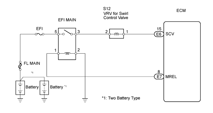
WIRING DIAGRAM
INSPECTION PROCEDURE
Tech Tips
Read freeze frame data using the intelligent tester. Freeze frame data records the engine conditions when a malfunction is detected. When troubleshooting, freeze frame data can help determine if the vehicle was running or stopped, if the engine was warmed up or not, and other data from the time the malfunction occurred.
Note
If the ECM is replaced, the new ECM needs initialization Click here.
PROCEDURE
-
CHECK ANY OTHER DTCS OUTPUT (IN ADDITION TO DTC P2006)
-
Connect an intelligent tester to the DLC3.
-
Turn the ignition switch ON and turn the tester ON.
-
Select the following menu items: Powertrain / Engine and ECT / DTC.
-
Read DTCs.
Result Display (DTC Output) Proceed To P2006 A P2006 and other DTCs B
B 
GO TO DTC CHART
A 
-
-
CHECK CONNECTION OF VACUUM HOSE
-
Check the vacuum hose connection of the swirl control valve system.
NG
REPAIR OR REPLACE VACUUM HOSE
OK
-
-
PERFORM ACTIVE TEST USING INTELLIGENT TESTER (VACUUM SWITCHING VALVE FOR SWIRL CONTROL VALVE)
-
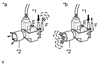
Text in Illustration *1 Air *2 Air Filter *a VSV: ON *b VSV: OFF Connect an intelligent tester to the DLC3.
-
Disconnect the vacuum hoses from the VSV for swirl control valve.
-
Turn the ignition switch ON and turn the tester ON.
-
Select the following menu items: Powertrain / Engine and ECT / Active Test / Activate the VSV for Swirl Control Valve.
-
Check the operation.
OK When VSV for swirl control valve is ON, air from port E flows out through port F. When VSV for swirl control valve is OFF, air from port E flows out through air filter. -
Reconnect the vacuum hoses to the VSV for swirl control valve.
NG
REPLACE VACUUM SWITCHING VALVE FOR SWIRL CONTROL VALVE
OK
-
-
INSPECT VACUUM SWITCHING VALVE FOR SWIRL CONTROL VALVE (RESISTANCE)
-
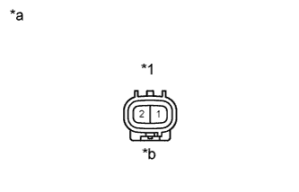
Text in Illustration *1 VSV for Swirl Control Valve Connector *a Component Side *b Front View Disconnect the S12 VSV for swirl control valve connector.
-
Measure the resistance of the VSV for swirl control valve.
Standard resistance Tester Connection Condition Specified Condition 1 - 2 20°C (68°F) 37 to 44 Ω -
Reconnect the VSV for swirl control valve connector.
NG
REPLACE VACUUM SWITCHING VALVE FOR SWIRL CONTROL VALVE
OK
-
-
CHECK HARNESS AND CONNECTOR (VACUUM SWITCHING VALVE FOR SWIRL CONTROL VALVE - ECM)
-
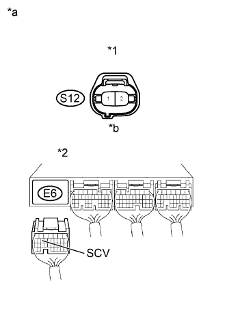
Text in Illustration *1 VSV for Swirl Control Valve Connector *2 ECM Connector *a Wire Harness Side *b Front View Disconnect the S12 VSV for swirl control valve connector.
-
Disconnect the E6 ECM connector.
-
Check the resistance.
Standard resistance (Check for open) Tester Connection Specified Condition S12-1 - E6-15 (SCV) Below 1 Ω Standard resistance (Check for short) Tester Connection Specified Condition S12-1 or E6-15 (SCV) - Body ground 10 kΩ or higher -
Reconnect the VSV for swirl control valve connector.
-
Reconnect the ECM connector.
NG
REPAIR OR REPLACE HARNESS OR CONNECTOR
OK
-
-
CHECK HARNESS AND CONNECTOR (VACUUM SWITCHING VALVE FOR SWIRL CONTROL VALVE - MAIN RELAY)
-
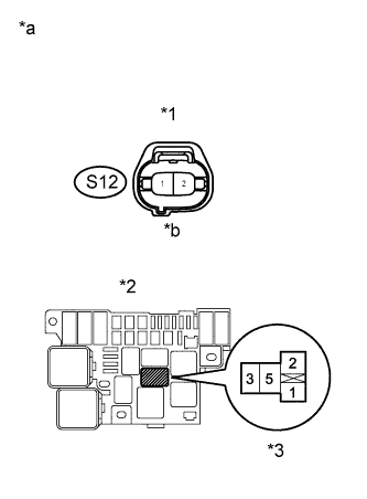
Text in Illustration *1 VSV for Swirl Control Valve Connector *2 Relay Block No. 2 *3 EFI MAIN Relay *a Wire Harness Side *b Front View Disconnect the S12 VSV for swirl control valve connector.
-
Remove the EFI MAIN relay from the R/B No. 2.
-
Check the resistance.
Standard resistance (Check for open) Tester Connections Specified Conditions S12-2 - R/B No. 2 (EFI MAIN relay terminal 3) Below 1 Ω Standard resistance (Check for short) Tester Connections Specified Conditions S12-2 or R/B No. 2 (EFI MAIN relay terminal 3) - Body ground 10 kΩor higher -
Reconnect the VSV for swirl control valve connector.
-
Reinstall the EFI MAIN relay.
NG
REPAIR OR REPLACE HARNESS OR CONNECTOR
OK
-
-
INSPECT INTAKE MANIFOLD (SWIRL CONTROL VALVE OPERATION)
Inspect the intake manifold (swirl control valve) Click here.
OK The valve is not stuck and does not have heavy carbon deposits.
NG
REPLACE INTAKE MANIFOLD
OK
-
CHECK EGR VALVE ASSEMBLY
Check the EGR valve Click here.
OK The valve is not stuck and does not have heavy carbon deposits.
NG
REPLACE EGR VALVE ASSEMBLY
OK
-
INSPECT INTAKE AIR TEMPERATURE SENSOR
-
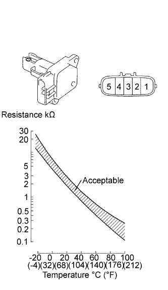
Remove the MAF meter.
-
Measure the resistance of the IAT sensor.
Standard resistance Tester Connection Condition Specified Condition 4 - 5 -20°C (-4°F) 13.6 to 18.4 kΩ 20°C (68°F) 2.21 to 2.69 kΩ 60°C (140°F) 0.49 to 0.67 kΩ -
Reinstall the MAF meter.
NG
REPLACE MASS AIR FLOW METER
OK
-
-
CHECK ANY OTHER DTCS OUTPUT (IN ADDITION TO DTC P2006)
-
Connect an intelligent tester to the DLC3.
-
Turn the ignition switch ON and turn the tester ON.
-
Select the following menu items: Powertrain / Engine and ECT / DTC.
-
Read DTCs.
Result Display (DTC Output) Proceed To P2006 A No output B
B
GO TO DTC CHART
A 
REPLACE ECM
-