ECD SYSTEM, Diagnostic DTC:P0627
| DTC Code | DTC Name |
|---|---|
| P0627 | Fuel Pump Control Circuit / Open |
DESCRIPTION
Tech Tips
For more information on the supply pump (suction control valve) and the common rail system, refer to the system description Click here.
| DTC No. | DTC Detection Condition | Trouble Area |
|---|---|---|
| P0627 | Open or short in suction control valve circuit for more than 0.5 seconds (1 trip detection logic) |
|
Tech Tips
When DTC P0627 is set, check the internal fuel pressure of the common rail by entering the following menus on the intelligent tester : Powertrain / Engine and ECT / Data List / Fuel Press.
| Engine Speed | Fuel Pressure |
|---|---|
| Idling | Approximately 30 to 40 MPa |
| 3,000 rpm (No engine load) | Approximately 50 to 70 MPa |
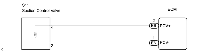
WIRING DIAGRAM
INSPECTION PROCEDURE
Tech Tips
Read freeze frame data using the intelligent tester. Freeze frame data records the engine condition when a malfunction is detected. When troubleshooting, freeze frame data can help determine if the vehicle was moving or stationary, if the engine was warmed up or not, and other data from the time the malfunction occurred.
Note
-
If the supply pump is replaced, the ECM needs initialization Click here.
-
If the ECM is replaced, the new ECM needs initialization Click here.
PROCEDURE
-
INSPECT SUPPLY PUMP ASSEMBLY (SUCTION CONTROL VALVE)
-
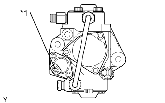
Text in Illustration *1 Suction Control Valve Disconnect the S11 suction control valve connector.
-
Measure the resistance of the suction control valve.
Standard resistance Tester Connection Specified Condition 1 - 2 1.9 to 2.3 Ω at 20°C (68°F) -
Reconnect the suction control valve connector.
NG 
REPLACE SUCTION CONTROL VALVE
OK 
-
-
CHECK HARNESS AND CONNECTOR (SUCTION CONTROL VALVE - ECM)
-
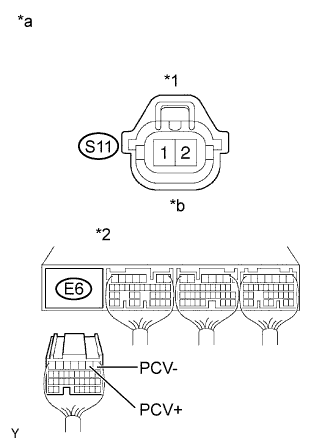
Text in Illustration *1 Suction Control Valve Connector *2 ECM Connector *a Wire Harness Side *b Front View Disconnect the S11 suction control valve connector.
-
Disconnect the E6 ECM connector.
-
Check the resistance.
Standard resistance (Check for open) Tester Connection Specified Condition S11-1 - E6-2 (PCV+) Below 1 Ω S11-2 - E6-1 (PCV-) Below 1 Ω Standard resistance (Check for short) Tester Connection Specified Condition S11-1 or E6-2 (PCV+) - Body ground 10 kΩor higher S11-2 or E6-1 (PCV-) - Body ground 10 kΩor higher -
Reconnect the suction control valve connector.
-
Disconnect the ECM connector.
NG
REPAIR OR REPLACE HARNESS OR CONNECTOR
OK
-
-
INSPECT ECM (PCV VOLTAGE)
-
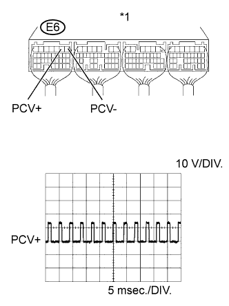
Text in Illustration *1 ECM Connector While cranking or idling the engine, check the waveform of the ECM connector using an oscilloscope.
OK Tester Connection Specified Condition E6-2 (PCV+) - E6-1 (PCV-) Correct waveform is as shown Tool Setting Condition 10 V/DIV., 5 msec./DIV. Idling or cranking with warm engine Tech Tips
The waveform varies depending on the suction control valve operation.
NG
REPLACE ECM
OK 
CHECK FOR INTERMITTENT PROBLEMS
-