ECD SYSTEM, Diagnostic DTC:P0516, P0517
| DTC Code | DTC Name |
|---|---|
| P0516 | Battery Temperature Sensor Circuit Low |
| P0517 | Battery Temperature Sensor Circuit High |
DESCRIPTION
The battery thermometer sensor is installed on the battery negative terminal to detect battery temperature.
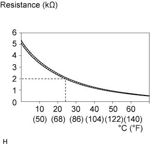
A thermistor is integrated into the battery thermometer sensor, and the resistance of the thermistor in the battery thermometer sensor changes according to the battery temperature.
The resistance of the thermistor in the battery current sensor decreases as the battery temperature increases. The resistance increases as the temperature decreases.
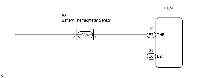
The battery thermometer sensor is connected to the ECM. The ECM supplies 5 V from the THB terminal to the battery thermometer sensor through resistor R.
The battery thermometer sensor and resistor R are connected in series. This results in changes in the voltage supplied from the THB terminal when the resistance changes according to the battery temperature.
The ECM determines the battery temperature according to changes of voltage. When the battery temperature is high, the ECM determines to reduce the amount of current supplied from the generator in order to protect the battery.
| DTC No. | DTC Detection Condition | Trouble Area |
|---|---|---|
| P0516 | Battery thermometer sensor output value is 0.2 V or less for 0.5 seconds or more with the ignition switch ON (1 trip detection logic) |
|
| P0517 | Battery thermometer sensor output value is 4.8 V or more for 0.5 seconds or more with the ignition switch ON (1 trip detection logic) |
|
WIRING DIAGRAM
INSPECTION PROCEDURE
Note
After replacing the ECM, the new ECM needs registration Click here and initialization Click here.
Tech Tips
If DTCs relating to different systems are output, and they share terminal E2 as their ground, check this ground circuit first.
PROCEDURE
-
INSPECT BATTERY THERMOMETER SENSOR
-
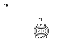
Text in Illustration *1 Battery Thermometer Sensor *a Component Side Disconnect the battery thermometer sensor connector.
-
Measure the resistance of the battery thermometer sensor.
Standard resistance Tester Connection Condition Specified Condition 1 - 2 20 to 30°C (68 to 86°F) 1.91 to 2.05 kΩ -
Reconnect the battery thermometer sensor connector.
NG 
REPLACE BATTERY THERMOMETER SENSOR
OK 
-
-
CHECK HARNESS AND CONNECTOR (BATTERY THERMOMETER SENSOR - ECM)
-
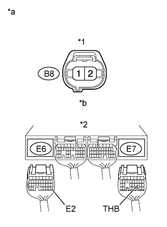
Text in Illustration *1 Battery Thermometer Sensor Connector *2 ECM Connector *a Wire Harness Side *b Front View Disconnect the B8 battery thermometer sensor connector.
-
Disconnect the E6 and E7 ECM connectors.
-
Check the resistance.
Standard resistance (Check for open) Tester Connection Specified Condition B8-1 - E7-20 (THB) Below 1 Ω B8-2 - E6-28 (E2) Below 1 Ω Standard resistance (Check for short) Tester Connection Specified Condition B8-1 or E7-20 (THB) - Body ground 10 kΩ or higher -
Reconnect the battery thermometer sensor connector.
-
Reconnect the ECM connector.
NG
REPAIR OR REPLACE HARNESS OR CONNECTOR
OK 
REPLACE ECM
-