ECD SYSTEM, Diagnostic DTC:P2120, P2122, P2123, P2125, P2127, P2128, P2138
| DTC Code | DTC Name |
|---|---|
| P2120 | Throttle / Pedal Position Sensor / Switch "D" Circuit |
| P2122 | Throttle / Pedal Position Sensor / Switch "D" Circuit Low Input |
| P2123 | Throttle / Pedal Position Sensor / Switch "D" Circuit High Input |
| P2125 | Throttle / Pedal Position Sensor / Switch "E" Circuit |
| P2127 | Throttle / Pedal Position Sensor / Switch "E" Circuit Low Input |
| P2128 | Throttle / Pedal Position Sensor / Switch "E" Circuit High Input |
| P2138 | Throttle / Pedal Position Sensor / Switch "D" / "E" Voltage Correlation |
DESCRIPTION
Tech Tips
-
This is the repair procedure for the accelerator pedal position sensor.
-
This electrical throttle system does not use a throttle cable.
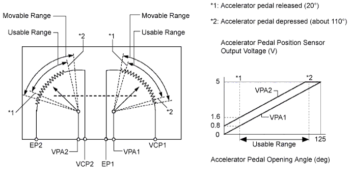
The accelerator pedal position sensor is mounted on the accelerator pedal and detects the opening angle of the accelerator pedal. It has 2 sensors to detect the accelerator position and a malfunction of the accelerator position sensor.
In the accelerator pedal position sensor, the voltage applied to pedal terminals VPA1 and VPA2 of the ECM changes between 0 V and 5 V in proportion to the opening angle of the accelerator pedal. The VPA1 is a signal to indicate the actual accelerator pedal opening angle which is used for the engine control, and the VPA2 is a signal to indicate the information about the opening angle which is used for detecting malfunctions. The ECM judges the current opening angle of the accelerator pedal using signals from terminals VPA1 and VPA2, and the ECM uses them as one of the conditions to control the injection volume and diesel throttle valve position.
| DTC No. | DTC Detection Condition (All of following are 1 trip detection logic) |
Trouble Area |
|---|---|---|
| P2120 | Condition (a) continues for 0.4 seconds or more: (a) (VPA is 0.4 V or less) or (VPA is 4.8 V or more) |
|
| P2122 | VPA is 0.4 V or less for 0.5 seconds or more when VPA2 output indicates accelerator pedal is opened |
|
| P2123 | Condition (a) continues for 2.0 seconds or more: (a) VPA1 is 4.8 V or more |
|
| P2125 | Condition (a) continues for 0.5 seconds or more: (a) (VPA2 is 1.2 V or less) or (VPA2 is 4.8 V or more) |
|
| P2127 | VPA2 is 1.2 V or less for 0.5 seconds or more when VPA output indicates accelerator pedal is opened |
|
| P2128 | Conditions (a) and (b) continue for 2.0 seconds or more: (a) VPA2 is 4.8 V or more (b) VPA is 0.4 V or more and VPA1 is 3.45 V or less |
|
| P2138 | Condition (a) or (b) continues for 2.0 seconds or more: (a) Difference between VPA and VPA2 is 0.02 V or less (b) VPA is 0.4 V or less and VPA2 is 1.2 V or less |
|
Tech Tips
When DTC P2120, P2122, P2123, P2125, P2127, P2128 or P2138 is detected, check the output voltage of the accelerator pedal position sensor by selecting the following menu items on the intelligent tester: Powertrain / Engine / Data List / Accelerator Position No. 1 and Accelerator Position No. 2.
| - | Accelerator pedal position expressed as voltage output | |||
|---|---|---|---|---|
| - | Accelerator pedal released | Accelerator pedal depressed | ||
| Trouble Area | Accelerator Position No.1 | Accelerator Position No. 2 | Accelerator Position No. 1 | Accelerator Position No. 2 |
| VCP circuit open | 0 to 0.2 V | 0 to 0.2 V | 0 to 0.2 V | 0 to 0.2 V |
| VPA circuit open or ground short | 0 to 0.2 V | 1.2 to 2.0 V | 0 to 0.2 V | 3.4 to 5.0 V |
| VPA2 circuit open or ground short | 0.5 to 1.1 V | 0 to 0.2 V | 2.6 to 4.5 V | 0 to 0.2 V |
| EP circuit open | 4.5 to 5.0 V | 4.5 to 5.0 V | 4.5 to 5.0 V | 4.5 to 5.0 V |
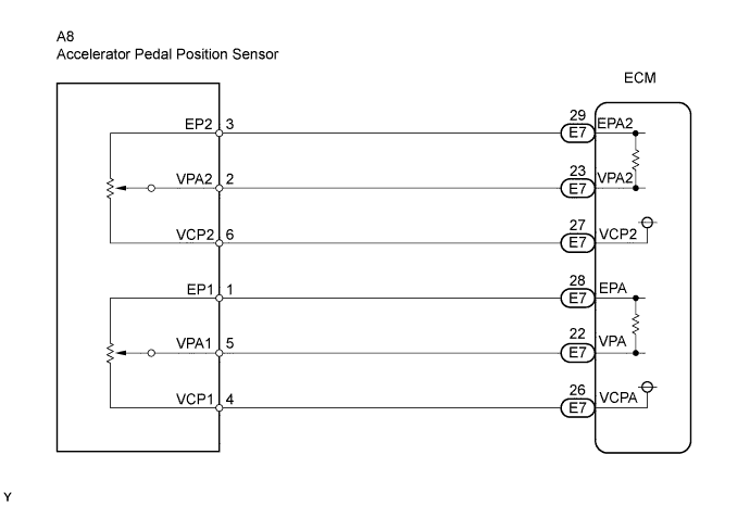
WIRING DIAGRAM
INSPECTION PROCEDURE
Tech Tips
Read freeze frame data using an intelligent tester. Freeze frame data records the engine condition when a malfunction is detected. When troubleshooting, freeze frame data can help determine if the vehicle was moving or stationary, if the engine was warmed up or not, and other data from the time the malfunction occurred.
Note
After replacing the ECM, the new ECM needs registration Click here and initialization Click here.
PROCEDURE
-
READ VALUE USING INTELLIGENT TESTER (ACCELERATOR POSITION NO. 1, ACCELERATOR POSITION NO. 2)
-
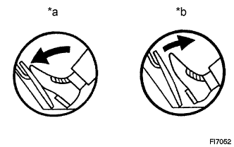
Text in Illustration *a Depressed *b Released Connect the intelligent tester to the DLC3.
-
Turn the ignition switch ON and turn the tester ON.
-
Select the following menu items: Powertrain / Engine / Data List / Accelerator Position No. 1 and Accelerator Position No. 2.
-
Read the value displayed on the tester when the accelerator pedal is released and depressed.
Standard voltage Accelerator Pedal Operations Accelerator Position No. 1 Accelerator Position No. 2 Released → Depressed → Released 0.5 to 4.6 V 0.9 to 5.0 V Difference between Accelerator Position No. 1 and Accelerator Position No. 2 is greater than 0.02 V Difference between Accelerator Position No. 1 and Accelerator Position No. 2 is greater than 0.02 V
OK 
CHECK WHETHER DTC OUTPUT RECURS (ACCELERATOR PEDAL POSITION SENSOR DTC IS OUTPUT AGAIN) Click here
NG 
-
-
INSPECT ACCELERATOR PEDAL ASSEMBLY (ACCELERATOR PEDAL POSITION SENSOR)
-
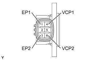
Disconnect the A8 Accelerator Pedal Position (APP) sensor connector.
-
Measure the resistance between each terminal.
Standard resistance Tester Connection Specified Condition 3 - 6 1.5 to 6.0 kΩ at 20°C (68°F) 1 - 4 1.5 to 6.0 kΩ at 20°C (68°F) -
Reconnect the APP sensor connector.
NG 
REPLACE ACCELERATOR PEDAL ASSEMBLY
OK
-
-
INSPECT ECM (VCP1 AND VCP2 VOLTAGE)
-
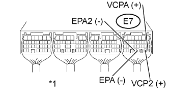
Text in Illustration *1 ECM Connector Disconnect the A8 APP sensor connector.
-
Turn the ignition switch ON.
-
Measure the voltage of the E7 ECM connector.
Standard voltage Tester Connection Specified Condition E7-26 (VCPA) - E7-28 (EPA) 4.5 to 5.0 V E7-27 (VCP2) - E7-29 (EPA2) 4.5 to 5.0 V -
Reconnect the APP sensor connector.
NG
REPLACE ECM
OK
-
-
INSPECT ECM (VPA1 AND VPA2 VOLTAGE)
-
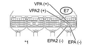
Text in Illustration *1 ECM Connector Turn the ignition switch ON.
-
Measure the voltage of the E7 ECM Connector.
Standard voltage Tester Connection Accelerator Pedal Operation Specified Condition E7-22 (VPA) - E7-28 (EPA) Released 0.5 to 1.1 V Depressed 3.0 to 4.6 V E7-23 (VPA2) - E7-29 (EPA2) Released 0.9 to 2.3 V Depressed 3.4 to 5.0 V
NG
CHECK HARNESS AND CONNECTOR (ACCELERATOR PEDAL POSITION SENSOR - ECM) Click here
OK 
REPLACE ECM
-
-
CHECK HARNESS AND CONNECTOR (ACCELERATOR PEDAL POSITION SENSOR - ECM)
-
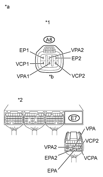
Text in Illustration *1 Accelerator Pedal Position Sensor Connector *2 ECM Connector *a Wire Harness Side *b Front View Disconnect the A8 APP sensor connector.
-
Disconnect the E7 ECM connector.
-
Check the resistance.
Standard resistance (Check for open) Tester Connections Specified Conditions A8-4 (VCP1) - E7-26 (VCPA) Below 1 Ω A8-5 (VPA1) - E7-22 (VPA) Below 1 Ω A8-1 (EP1) - E7-28 (EPA) Below 1 Ω A8-6 (VCP2) - E7-27 (VCP2) Below 1 Ω A8-2 (VPA2) - E7-23 (VPA2) Below 1 Ω A8-3 (EP2) - E7-29 (EPA2) Below 1 Ω Standard resistance (Check for short) Tester Connections Specified Conditions A8-4 (VCP1) or E7-26 (VCPA) - Body ground 10 kΩ or higher A8-5 (VPA1) or E7-22 (VPA) - Body ground 10 kΩ or higher A8-1 (EP1) or E7-28 (EPA) - Body ground 10 kΩ or higher A8-6 (VCP2) or E7-27 (VCP2) - Body ground 10 kΩ or higher A8-2 (VPA2) or- E7-23 (VPA2) - Body ground 10 kΩ or higher A8-3 (EP2) or E7-29 (EPA2) - Body ground 10 kΩ or higher -
Reconnect the APP sensor connector.
-
Reconnect the ECM connector.
NG
REPAIR OR REPLACE HARNESS OR CONNECTOR
OK
-
-
CHECK WHETHER DTC OUTPUT RECURS (ACCELERATOR PEDAL POSITION SENSOR DTC IS OUTPUT AGAIN)
-
Clear the DTC Click here.
-
Start the engine.
-
Let the engine idle for 15 seconds or more.
-
Select the following menu items: Powertrain / Engine / DTC.
-
Read DTCs.
Result Display (DTC Output) Proceed to P2120, P2122, P2123, P2125, P2127, P2128 or P2138 is output again A P2120, P2122, P2123, P2125, P2127, P2128 or P2138 is not output B
B
CHECK FOR INTERMITTENT PROBLEMS
A
REPLACE ECM
-