REAR DIFFERENTIAL CARRIER ASSEMBLY REASSEMBLY

-
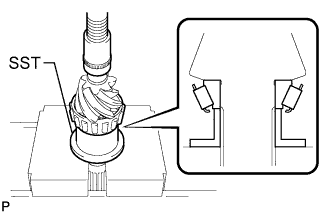
INSTALL FRONT BEARING OUTER RACE
-
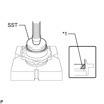
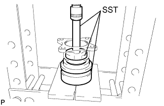
Text in Illustration *1 Front Bearing Outer Race Using SST and a press, press in the front bearing outer race onto the bearing cage.
- SST
- 09518-36020
Tech Tips
Apply gear oil to the front bearing outer race.
-
-
INSTALL REAR BEARING OUTER RACE
-
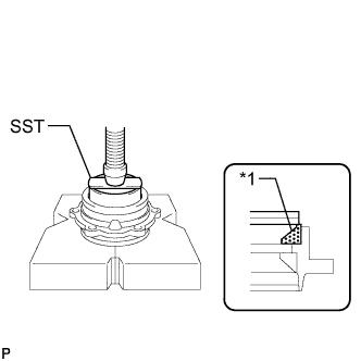
Text in Illustration *1 Rear Bearing Outer Race Using SST and a press, press in the rear bearing outer race onto the bearing cage.
- SST
- 09223-78010
Tech Tips
Apply gear oil to the rear bearing outer race.
-
-
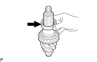
INSTALL PILOT BEARING INNER RACE
-
Using SST and a press, press in the pilot bearing inner race onto the differential drive pinion.
- SST
- 09316-60011 ( 09316-00011, 09316-00071 )
Tech Tips
Apply gear oil to the pilot bearing inner race.
-
Using a snap ring expander, install a new snap ring in the groove on the differential drive pinion tip.
Note
When installing the snap ring, use a cloth or equivalent to prevent the snap ring from flying off.
-
-
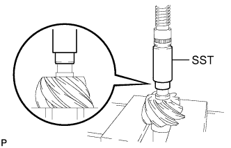
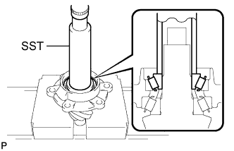
INSTALL REAR DRIVE PINION REAR TAPERED ROLLER BEARING
-
Using SST and a press, install the rear drive pinion rear tapered roller bearing onto the differential drive pinion.
- SST
- 09315-00022
Tech Tips
Apply gear oil to the inner race.
-
-
INSTALL REAR DIFFERENTIAL DRIVE PINION BEARING SPACER
-
Install the rear differential drive pinion bearing spacer.
-
-
INSTALL REAR DRIVE PINION FRONT TAPERED ROLLER BEARING
-
Using SST and a press, install the differential drive pinion bearing cage and rear drive pinion front tapered roller bearing onto the differential drive pinion.
- SST
- 09316-60011
Tech Tips
Apply gear oil to the inner race.
-
-
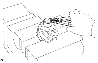
INSPECT DIFFERENTIAL DRIVE PINION PRELOAD
-
Apply the gear oil to the thread of the rear drive pinion nut.
-
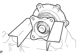
Install the rear drive pinion companion flange sub-assembly and rear drive pinion nut to the differential drive pinion. Hold the drive pinion companion flange sub-assembly in a vise with aluminum plates in between.
-
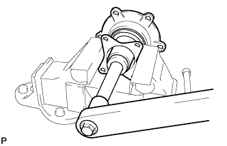
Using a 41 mm deep socket wrench, tighten the rear drive pinion nut.
- Torque:
- 435 N*m { 4437 kgf*cm, 321 ft.*lbf }
-
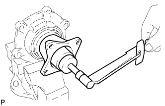
Using a torque wrench, measure the preload at the rear drive pinion nut part.
Preload: New bearing Reused bearing 1.48 to 1.96 N*m
(15 to 20 kgf*cm, 13 to 17 in.*lbf)
0.98 to 1.47 N*m
(10 to 15 kgf*cm, 9 to 13 in.*lbf)
Note
-
Do not install an oil seal before preload measurement.
-
When either of the bearings is new, use the preload for a new bearing.
-
-
When the measured value is not within the specified range, select the rear differential drive pinion bearing spacer thickness to adjust the preload.
Spacer thickness: Part No. Thickness 41231-37420 14.400 mm (0.5669 in.) 41231-37430 14.425 mm (0.5679 in.) 41231-37440 14.450 mm (0.5689 in.) 41231-37450 14.475 mm (0.5699 in.) 41231-37460 14.500 mm (0.5709 in.) 41231-37470 14.525 mm (0.5718 in.) 41231-37480 14.550 mm (0.5728 in.) 41231-37490 14.575 mm (0.5738 in.) 41231-37500 14.600 mm (0.5748 in.) 41231-37510 14.625 mm (0.5758 in.) 41231-37520 14.650 mm (0.5768 in.) 41231-37530 14.675 mm (0.5778 in.) 41231-37540 14.700 mm (0.5787 in.) 41231-37550 14.725 mm (0.5797 in.) 41231-37560 14.750 mm (0.5807 in.) 41231-37570 14.775 mm (0.5817 in.) 41231-37580 14.800 mm (0.5827 in.) 41231-37590 14.825 mm (0.5837 in.) 41231-37600 14.850 mm (0.5846 in.) 41231-37610 14.875 mm (0.5856 in.)
-
-
INSTALL REAR DIFFERENTIAL CARRIER OIL SEAL
-
After preload adjustment, remove the rear drive pinion companion flange sub-assembly and use a brass bar and a plastic-faced hammer to tap in a new rear differential carrier oil seal into the differential drive pinion bearing cage.
Note
Tap the rear differential carrier oil seal uniformly to drive it in.
-
Apply MP grease to the rear differential carrier oil seal lip.
-
-
INSTALL REAR DIFFERENTIAL DUST DEFLECTOR
-
Using SST and a press, install a new rear differential dust deflector to the rear drive pinion companion flange sub-assembly.
- SST
- 09950-60010 ( 09951-00610 )
- 09950-70010 ( 09951-07100 )
- 09527-17011
Note
Perform this procedure only when the dust deflector has been removed.
-
-
INSTALL REAR DRIVE PINION COMPANION FLANGE SUB-ASSEMBLY
-
Apply MP grease to the rear differential dust deflector lip.
-
Install the rear drive pinion companion flange sub-assembly, and tighten a new rear drive pinion nut using a deep socket wrench (41 mm).
- Torque:
- 435 N*m { 4436 kgf*cm, 320 ft.*lbf }
-
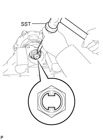
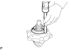
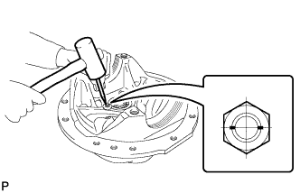
Using SST and a hammer, stake the rear drive pinion nut completely while aligning the 2 shaft grooves.
- SST
- 09930-00010
Note
-
-
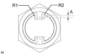
Completely attach to the shaft ends (R1, R2) as shown in the figure.
-
Stake so that dimension A shown in the figure will be 1.5 mm (0.0585 in.) or more.
-
Make sure that there are no breaks in the staked portion of the lock nut.
-
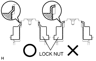
Stake from the bottom as shown in the figure. Staking only the tip is not sufficient.
-
Using a 41 mm deep socket wrench and torque wrench, measure the drive pinion preload (starting torque) with the oil seal installed.
Tech Tips
The measured value should be used to calculate the side bearing preload after installing the drive pinion assembly to the differential carrier.
-
-
INSTALL O-RING
-
Using a scraper, clean off dust on the connecting surfaces of the bearing cage, differential carrier and shim(s).
Note
Be careful not to damage the installation surface.
-
Apply MP grease to a new O-ring.
-
Install the O-ring to the differential drive pinion bearing cage.
Note
Be careful not to damage the O-ring.
-
-
INSTALL DIFFERENTIAL CASE
-
Apply gear oil to the sliding surfaces of the rear differential side gear thrust washer, rear differential side gear and differential case LH.
-
Install the rear differential side gear thrust washer and the rear differential side gear on the differential case LH.
-
Apply gear oil to the sliding surfaces of the rear differential spider, 4 rear differential pinions, 4 rear differential side gear thrust washers.
-
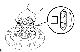
Install the 4 rear differential pinions and thrust washers to the rear differential spider.
-
Install the rear differential spider with the 4 rear differential pinions and 4 rear differential pinion thrust washers on the differential case LH.
-
Apply gear oil to the sliding surfaces of the rear differential side gear thrust washer, rear differential side gear and differential case RH.
-
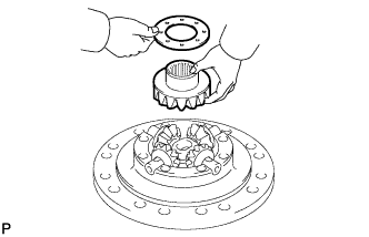
Install the rear differential side gear and rear differential pinion thrust washer to the differential case RH.
-
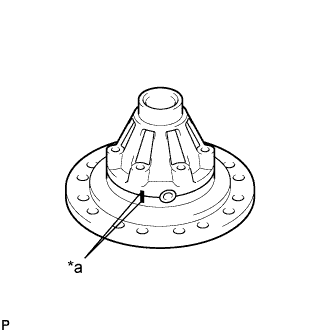
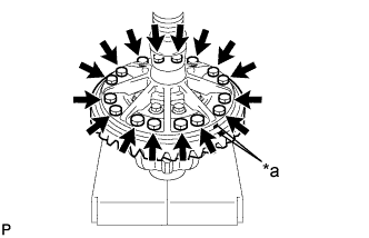
Text in Illustration *a Matchmark Align the matchmarks on the differential case LH and differential case RH.
-
Using a press, fix the differential case.
-
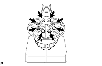
Apply adhesive to the threads of the 8 bolts and install them.
Adhesive Three Bond 1360K or equivalent - Torque:
- 190 N*m { 1937 kgf*cm, 140 ft.*lbf }
-
-
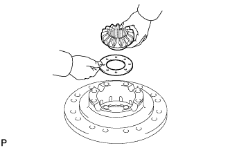
INSTALL DIFFERENTIAL RING GEAR
-
Clean the contact surfaces of the differential case and ring gear.
-
Clean the differential ring gear set bolt hole.
-
Text in Illustration *a Matchmark Align the matchmarks on the ring gear and the differential case LH.
-
Apply adhesive to the threads of the 16 bolts and install them.
Adhesive Three Bond 1360K or equivalent - Torque:
- 245 N*m { 2498 kgf*cm, 181 ft.*lbf }
-
-
INSTALL SIDE BEARING INNER RACE
-
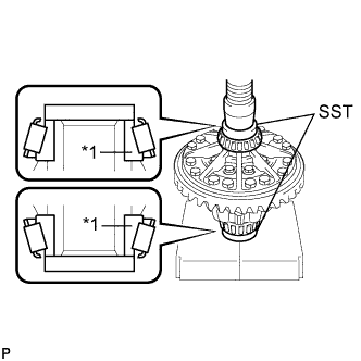
Text in Illustration *1 Side Bearing Inner Race Using SST and a press, install the 2 side bearing inner races to the differential case.
- SST
- 09950-60010 ( 09951-00640, 09951-00650 )
Note
Be careful not to apply load to the case of the side bearing inner races when installing.
-
-
INSTALL PILOT BEARING OUTER RACE
-
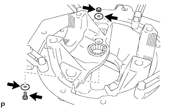
Install the pilot bearing outer race with the 2 bearing retainers, bolt and a new nut.
- Torque:
- 22 N*m { 224 kgf*cm, 16 ft.*lbf }
-
-
INSPECT CONICAL DISTANCE
-
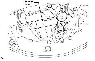
Using SST, measure the depth from the side bearing mounting surface to the drive pinion tip (this depth is called the conical distance).
- SST
- S0964-01022
Standard 27 mm (1.063 in.) Note
-
Before installing the differential drive pinion, record the machining error dimension stamped at the pinion tip and use it for calculation of the conical distance.
-
The conical distance is the standard dimension at the time of adjustment of the tooth contact of the differential drive pinion and ring gear, and the best tooth contact is obtained when setting is done with this dimension. For reasons of machining, a machining error dimension in regard to the norm dimension is stamped at the tip of the differential drive pinion, and the dimension under consideration of this machining error dimension and the norm dimension is called the standard dimension.
-
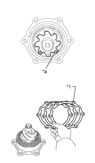
Text in Illustration *1 Drive Pinion Cage Shims *a Machining Error Dimension Adjustment is made by changing the thickness of the differential drive pinion cage shim according to the difference between the measuring value and the tightening torque (conical distance).
Standard dimension Norm dimension + machining error dimension Tech Tips
When the machining error stamp at the tip of the differential drive pinion is 39, the machining error dimension is 0.39 mm (0.153 in.) (norm dimension + machining error dimension = standard dimension [27 mm (1.063 in.)+ 0.39 mm (0.153 in.)) = 27.39 mm (1.078 in.)]).
Shim thickness Part No. Thickness 41153-37090 0.30 mm (0.0118 in.) 41153-37100 0.40 mm (0.0157 in.) 41153-37110 0.45 mm (0.0177 in.) 41153-37120 0.50 mm (0.0197 in.) -
Using a punch, stake the 2 portions of the pilot bearing lock nut.
-
-
INSTALL DRIVE PINION SUB-ASSEMBLY
-
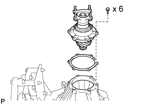
Install the drive pinion sub-assembly and the drive pinion cage shim(s) to the rear differential carrier assembly.
Note
Be careful not to damage the O-ring when installing.
-
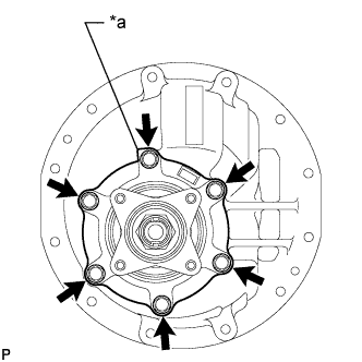
Text in Illustration *a Corner of Spotted Portion Tighten the 6 bolts to the drive pinion sub-assembly with the rear differential carrier assembly.
- Torque:
- 74 N*m { 760 kgf*cm, 55 ft.*lbf }
-
Using a punch, stake the 2 portions of the pilot bearing lock nut.
-
-
INSTALL REAR DIFFERENTIAL CASE SUB-ASSEMBLY
-
Place the 2 side bearing outer races on the 2 side bearings inner races.
Note
Check that the left and right outer races are not interchanged.
-
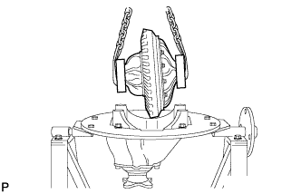
Using a chain block, install the rear differential case sub-assembly.
Tech Tips
Tilting the differential case, install the differential carrier.
-
Install the 2 rear differential bearing adjusting nuts on the carrier, make sure they are properly engaged.
Tech Tips
Making the 2 adjusting nuts horizontal to the side bearing, insert them from the top of the differential carrier.
-
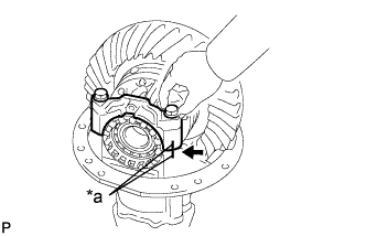
Text in Illustration *a Matchmark Align the matchmarks on the differential bearing cap and rear differential carrier. Temporarily install the differential side bearing caps with the 2 bolts.
Tech Tips
If the bearing cap does not tightly fit the carrier, the rear differential bearing adjusting nuts may not be properly engaged. Reinstall the rear differential bearing adjusting nuts if necessary.
-
-
ADJUST DIFFERENTIAL SIDE BEARING PRELOAD
-
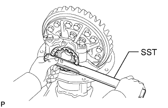
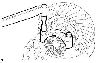
Using SST, fully tighten the rear differential bearing adjusting nut on the ring gear side. Loosen the nut by a 1/4 revolution.
- SST
- 09504-00011
-
Use the same procedures on the other side.
-
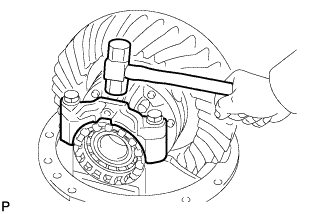
Using a plastic-faced hammer, lightly tap the top of the differential bearing cap so that the bearing fits.
-
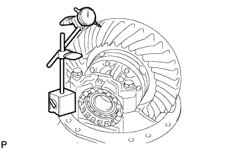
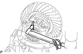
Using a dial indicator, measure the backlash.
Backlash: Reduction ratio Standard 4.625 0.20 to 0.28 mm (0.0078 to 0.0110 in.) 4.875 0.20 to 0.28 mm (0.0078 to 0.0110 in.) Tech Tips
Perform the measurement at 3 or more positions around the circumference of the ring gear, and adjust the side bearing preload as necessary.
-
The backlash should be adjusted by turning the left and right adjusting nuts by equal amounts. For example, if loosening the nut on the left side one notch, torque the nut on the right side one notch.
-
-
INSPECT TOOTH CONTACT BETWEEN RING GEAR AND DRIVE PINION
-
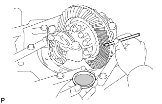
Coat 3 or 4 teeth at 3 different positions on the ring gear with prussian blue.
-
Turn the rear drive pinion companion flange sub-assembly in both directions to inspect the ring gear for proper tooth contact.
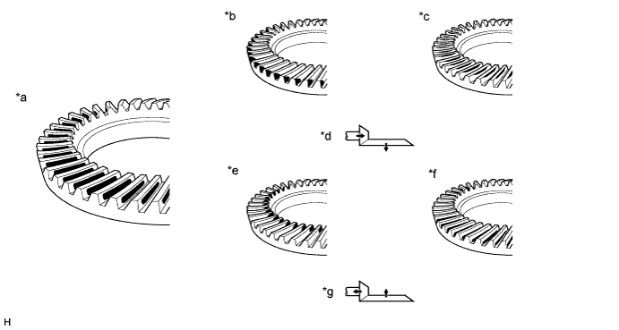
Text in Illustration *a Proper Contact *b Heel Contact *c Face Contact *d Select an adjusting washer that will shift the drive pinion closer to the ring gear (*b, *c) *e Toe Contact *f Flank Contact *g Select an adjusting washer that will shift the drive pinion away from the ring gear (*e, *f) - - If the teeth are not properly contacting, use the table below to select a proper shim (drive pinion cage shim) for correction.
Shim thickness: Part No. Thickness 41153-37090 0.30 mm (0.0118 in.) 41153-37100 0.40 mm (0.0157 in.) 41153-37110 0.45 mm (0.0177 in.) 41153-37120 0.50 mm (0.0197 in.) Tech Tips
Use one or more drive pinion cage shims for adjustment.
-
-
INSPECT TOTAL PRELOAD
-
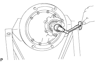
Using a 41 mm deep socket wrench and torque wrench, measure the total preload.
-
Calculate the side bearing preload by subtracting the drive pinion preload (starting torque after installing the oil seal) from the total preload. Check that the side bearing preload is within the specification.
Side bearing preload (new bearing): Reduction ratio Standard 4.625 0.32 to 0.42 N*m (3.3 to 4.2 kgf*cm, 2.9 to 3.7 in.*lbf) 4.875 0.31 to 0.40 N*m (3.2 to 4.1 kgf*cm, 2.7 to 3.5 in.*lbf) Side bearing preload (reused bearing): Reduction ratio Standard 4.625 0.22 to 0.31 N*m (2.3 to 3.1 kgf*cm, 2.0 to 2.7 in.*lbf) 4.875 0.21 to 0.30 N*m (2.1 to 3.0 kgf*cm, 1.8 to 2.6 in.*lbf) Tech Tips
-
Total preload = Drive pinion preload + Side bearing preload
-
When replacing both or either side bearings, use the standard of the side bearing preload (new bearing).
-
-
If the result is not as specified, then turn the left/right adjusting nuts using SST to adjust the preload.
- SST
- 09504-00011
Note
When adjusting with the adjusting nuts, turn them by an equal amount so that the backlash will not be incorrect.
-
Tighten the 2 differential bearing caps with the 4 bolts.
- Torque:
- 210 N*m { 2141 kgf*cm, 155 ft.*lbf }
-
Recheck the total preload.
-
Recheck the ring gear backlash.
Backlash: Reduction ratio Standard 4.625 0.20 to 0.28 mm (0.0078 to 0.0110 in.) 4.875 0.20 to 0.28 mm (0.0078 to 0.0110 in.)
-
-
INSTALL REAR DIFFERENTIAL BEARING ADJUSTING NUT LOCK
-
Install the 2 rear differential bearing adjusting nut locks on the 2 differential bearing caps.
- Torque:
- 22 N*m { 224 kgf*cm, 16 ft.*lbf }
-