MYY6S OUTPUT SHAFT REASSEMBLY

-
INSTALL NO. 2 TRANSMISSION HUB SLEEVE
Tech Tips
-
Thoroughly clean each part.
-
Secure the output shaft in a vise with the longer splines down. Be careful not to damage the polished surface.
-
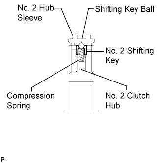
Install the 3 No. 2 synchromesh shifting keys and 3 compression springs to the No. 2 transmission clutch hub.
-
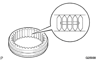
Install the No. 2 transmission hub sleeve onto the No. 2 transmission clutch hub until the hub sleeve is in light contact with the No. 2 synchromesh shifting keys.
Tech Tips
There are 3 grooves inside the No. 2 transmission hub sleeve. Assemble the parts so that the synchromesh shifting key balls can be positioned at the center of each groove.
-
While pressing in the 3 synchromesh shifting key balls, No. 2 synchromesh shifting keys, and compression springs, completely install the No. 2 transmission hub sleeve until the shifting key balls are fitted in the grooves on the hub sleeve.
-
-
INSTALL 2ND GEAR
-
Apply engine oil to the 2nd gear needle roller bearing, the thrust surface of the 2nd gear, and the tapered part of the synchronizer ring.
-
Install the 2nd gear and 2nd gear needle roller bearing to the output shaft.
-
Install the 3rd and 2nd inside ring, 3rd and 2nd outside ring, and No. 2 synchronizer ring so that the claws on the outside ring are fitted in the holes on the 2nd gear.
Tech Tips
Apply engine oil to both sides of the 3rd and 2nd inside and outside rings and the inside of the No. 2 synchronizer ring set.
-
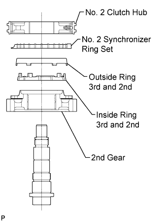
Using SST and a press, install the No. 2 transmission clutch hub and No. 2 transmission hub sleeve so that the 6 claws on the 3rd and 2nd inside ring are fitted in the 6 holes on the hub.
-
-
INSTALL 3RD GEAR
-
Install the No. 3 synchronizer ring set, 3rd and 2nd outside ring, and 3rd and 2nd inside ring so that the 6 claws on the inside ring are fitted in the 6 holes on the hub.
Tech Tips
Apply a sufficient amount of engine oil to the inside of the 3rd and 2nd inside and outside rings and No. 3 synchronizer ring set.
-
Apply engine oil to the 3rd gear needle roller bearing, the thrust surface of the 3rd gear, and the tapered part of the synchronizer ring.
-
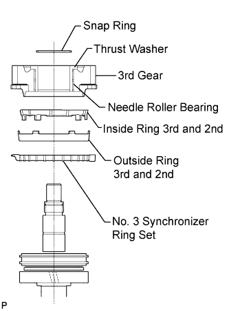
Using SST and a press, install the 3rd gear, 3rd gear needle roller bearing, and 3rd gear thrust washer so that the claws on the 3rd and 2nd outside ring are fitted in the holes on the 3rd gear.
-
-
INSTALL GEAR THRUST WASHER SHAFT SNAP RING
-
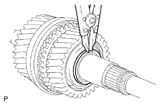
Using a snap ring expander, install the gear thrust washer shaft snap ring.
Note
-
If the snap ring is deformed or damaged, replace it with a new one.
-
Check that the snap ring is securely installed.
-
-
-
INSTALL NO. 3 SYNCHROMESH SHIFTING KEY
-
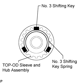
Securely install the 3 No. 3 synchromesh shifting keys into the grooves on the No. 3 synchronizer ring.
-
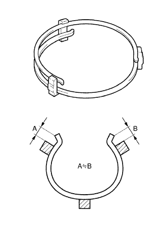
Install the 2 No. 3 synchromesh shifting key springs to the No. 3 synchromesh shifting keys.
Note
-
When installing the No. 3 synchromesh shifting key springs, leave an equal amount of excess space at both ends of each spring to prevent interference with the inside of the clutch hub.
-
Do not allow the openings of the No. 3 synchromesh shifting key springs to overlap.
-
-
Check that the clutch hub and hub sleeve slide smoothly.
-
-
INSTALL 4TH GEAR
-
Apply a sufficient amount of engine oil to the 4th gear needle roller bearing, the thrust surface of the 4th gear, and the tapered part of the synchronizer ring.
-
Install the 4th gear and 4th gear needle roller bearing.
-
Apply engine oil to the No. 3 synchronizer ring and install it.
-
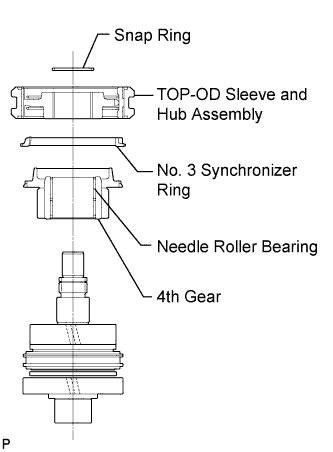
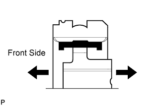
Using SST and a press, install the sleeve and hub assembly with the oil groove facing down so that the sleeve and hub assembly is fitted in the groove on the No. 3 synchronizer ring.
-
-
INSTALL NEEDLE ROLLER HOLE SNAP RING
-
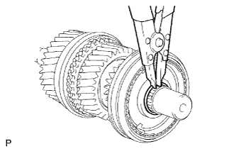
Using a snap ring expander, install the needle roller hole snap ring.
Note
-
If the snap ring is deformed or damaged, replace it with a new one.
-
Check that the snap ring is securely installed.
-
-
-
INSTALL NO. 1 TRANSMISSION HUB SLEEVE
-
Install the 3 No. 1 synchromesh shifting keys and 3 compression springs to the No. 1 transmission hub sleeve.
-
Install the No. 1 transmission hub sleeve onto the No. 1 transmission clutch hub until the hub sleeve is in light contact with the No. 1 synchromesh shifting keys.
Tech Tips
There are 3 grooves inside the No. 1 transmission hub sleeve. Assemble the parts so that the synchromesh shifting key balls can be positioned at the center of each groove.
-
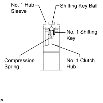
While pressing in the 3 synchromesh shifting key balls, No. 1 synchromesh shifting keys, and compression springs, completely install the No. 1 transmission hub sleeve until the shifting key balls are fitted in the grooves on the hub sleeve.
-
-
INSTALL 1ST GEAR
-
Apply engine oil to the 1st gear needle roller bearing, the thrust surface of the 1st gear, and the tapered part of the synchronizer ring.
-
Install the 1st gear and 1st gear needle roller bearing.
-
Install the low and reverse inside ring, low and reverse outside ring, and No. 1 synchronizer ring in this order so that the claws on the outside ring are fitted in the holes on the 1st gear.
-
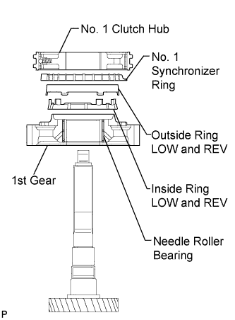
Using SST and a press, install the No. 1 transmission hub sleeve so that the 6 claws on the low and reverse inside ring are fitted in the 6 holes on the hub.
-
-
INSTALL REVERSE GEAR
-
Apply a sufficient amount of engine oil to the No. 2 synchronizer ring.
-
Install the No. 2 synchronizer ring so that the No. 1 transmission clutch hub and No. 1 transmission hub sleeve are fitted in the grooves on the No. 2 synchronizer ring.
-
Apply engine oil to the reverse gear bearing, the thrust surface of the reverse gear, and the tapered part of the synchronizer ring.
-
Using SST and a press, install the reverse gear, reverse gear bearing, and reverse gear bearing inner race so that the claws on the low and reverse inside ring are fitted in the holes on the synchronizer ring.
-
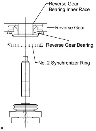
Install the output shaft spacer.
-
-
INSTALL OUTPUT SHAFT REAR BEARING
-
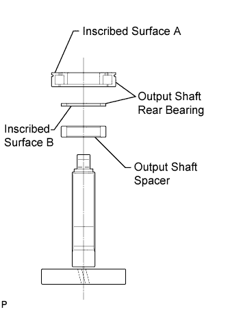
Using SST and a press, install the output shaft rear bearings with inscribed surface A facing up and inscribed surface B facing down.
-
-
INSTALL 6TH GEAR SUB-ASSEMBLY
-
Install the 6th gear sub-assembly.
Tech Tips
Check that the convex part is facing down.
-