MYY6S MANUAL TRANSMISSION UNIT REASSEMBLY

-
INSTALL TRANSMISSION FRONT BEARING RETAINER OIL SEAL
-
Apply engine oil to the outer circumference of a new transmission front bearing retainer oil seal.
-
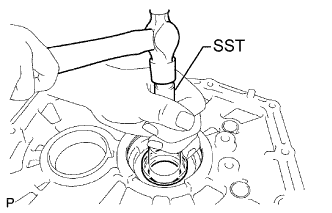
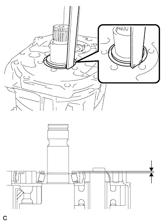
Using SST, install a new transmission front bearing retainer oil seal to the clutch housing.
- SST
- 09517-12010
Note
Do not damage the lip of the oil seal.
-
Coat the lip of the oil seal with MP grease.
-
-
INSTALL COUNTER GEAR FRONT BEARING
-
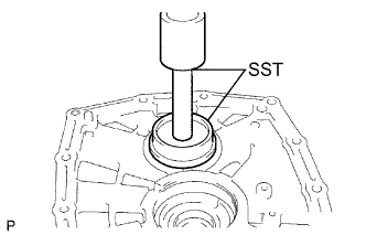
Using SST and a press, install a new counter gear front bearing (outer race).
- SST
- 09608-10010
- 09950-70010 ( 09951-07100 )
-
-
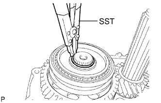
INSTALL CLUTCH HOUSING BUSHING
-
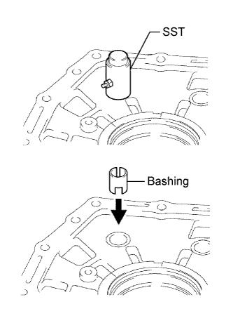
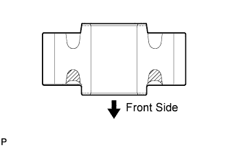
Using SST, install a new clutch housing bushing.
Note
Check that the bushing is installed in the direction shown in the illustration.
-
-
INSTALL OUTPUT SHAFT ASSEMBLY
-
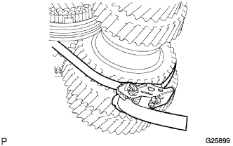
Using 2 straps with a ratcheting function such as tie down straps, securely bind the output shaft assembly, counter gear, and input shaft assembly at 2 places.
-
Install SST to the output shaft assembly with the output shaft rear set nut. Hang the assembly with cables.
Note
Be careful not to drop the input shaft assembly.
-
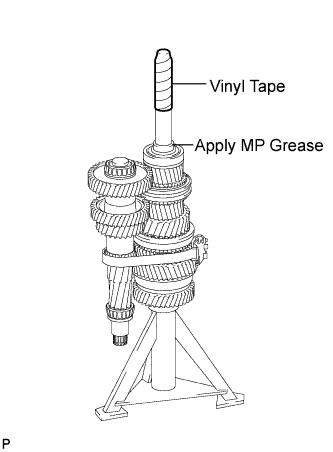
Place the input shaft assembly, output shaft assembly, and counter gear on a support stand with the input shaft assembly facing up.
-
Apply protective tape to the input shaft assembly.
-
Apply a small amount of MP grease to the contact surfaces of the lip of the transmission front bearing retainer oil seal and the input shaft assembly.
-
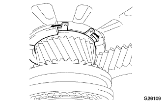
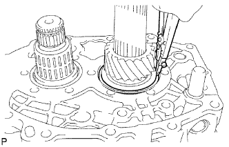
While expanding the front bearing shaft snap ring using a snap ring expander, insert the input shaft assembly, counter gear, and output shaft assembly as a unit into the clutch housing.
Note
-
Check that the snap ring is securely installed.
-
Carefully perform this operation to prevent damage to the transmission front bearing retainer oil seal.
-
-
-
INSTALL TRANSMISSION MAGNET
-
Install the transmission magnet to the clutch housing.
-
-
INSTALL SHIFT ARM BUSHING
-
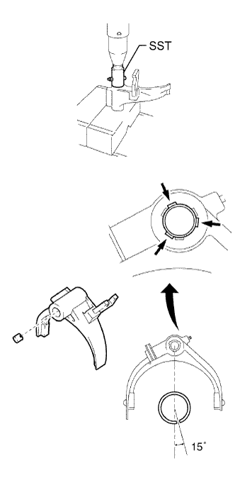
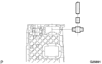
Using SST and a press, install a new shift arm bushing of the No. 3 gear shift fork.
Note
Check that the bushing is installed in the correct direction and at the correct angle as shown in the illustration.
-
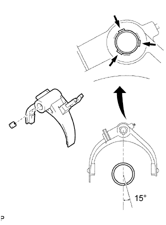
Using SST and a press, install a new shift arm bushing of the No. 2 gear shift fork.
Note
Check that the bushing is installed in the correct direction and at the correct angle as shown in the illustration.
-
Stake each bushing at 3 points other than the opening of the bushing and the previous staked points.
-
-
INSTALL NO. 1 GEAR SHIFT FORK SHAFT
-
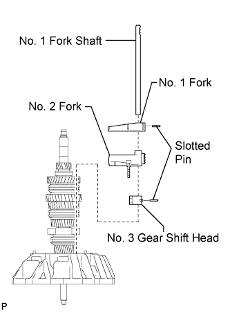
Install the No. 3 gear shift head, No. 2 gear shift fork and No. 1 gear shift fork to the No. 1 gear shift fork shaft.
-
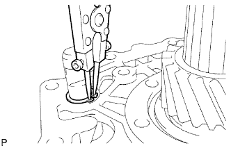
Align the holes for the 2 shift head slotted spring pins and tap in the slotted spring pins using a hammer.
Note
When tapping in the slotted spring pins, place a brass bar on the opposite side of the No. 1 gear shift fork shaft to prevent damage to other parts.
-
-
INSTALL NO. 2 GEAR SHIFT FORK SHAFT
-
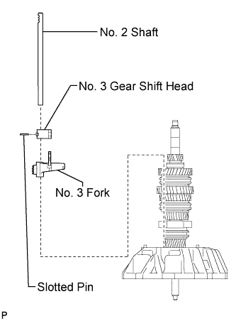
Install the No. 3 gear shift fork and No. 3 gear shift head to the No. 2 gear shift fork shaft.
-
Align the holes for the shift head slotted spring pin and tap in the slotted spring pin using a hammer.
Note
When tapping in the slotted spring pin, place a brass bar on the opposite side of the No. 2 gear shift fork shaft to prevent damage to other parts.
-
-
INSTALL MANUAL TRANSMISSION CASE
-
Clean the seal packing attached on the manual transmission case and clutch housing using a scraper and wire brush. Then remove the oil with non-residue type solvent or equivalent.
Note
Do not scratch the fitting surface.
-
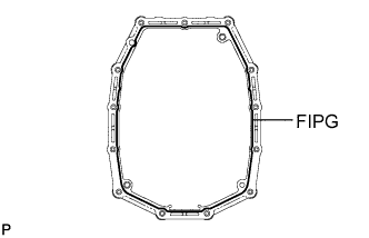
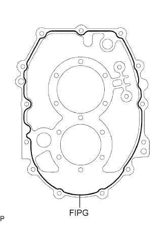
Apply FIPG to the manual transmission case as shown in the illustration.
Note
Before applying FIPG, remove any moisture, grease, and oil from the sealing surface. FIPG should be applied in a continuous line (width of 2 mm (0.079 in.) or more).
FIPG Toyota Genuine Seal Packing 1281, Three Bond 1281 or equivalent -
Install the 13 bolts and manual transmission case.
- Torque:
- 46 N*m { 470 kgf*cm, 34 ft.*lbf }
-
-
INSTALL COUNTER GEAR REAR BEARING
-
Install the counter gear rear bearing (outer race) to the transmission case.
-
-
INSTALL SNAP RING
-
Using a snap ring expander, install the snap ring.
Note
-
If the snap ring is deformed or damaged, replace it with a new one.
-
Check that the snap ring is securely installed.
-
-
-
ADJUST COUNTER GEAR BEARING PRELOAD
-
Install the counter gear shaft bearing setting shim.
-
Move the shift lever to the N position.
-
Place the transmission assembly with the clutch housing facing down.
-
Turn the counter gear 30 times or more to settle the bearing.
-
Measure the depth from the rear end face of the transmission case to the outer end face of the counter gear rear bearing at 3 points at 120-degree intervals. Calculate the average value.
-
Based on the average value, select the appropriate shim from the table below.
Measured depth mm (in.) Thickness mm (in.) 3.34 to 3.39 (0.1315 to 0.1335) 3.19 (0.126) 3.28 to 3.33 (0.1291 to 0.1311) 3.13 (0.123) 3.22 to 3.27 (0.1268 to 0.1287) 3.07 (0.121) 3.16 to 3.21 (0.1244 to 0.1264) 3.01 (0.119) 3.10 to 3.15 (0.1220 to 0.1240) 2.95 (0.116) 3.04 to 3.11 (0.1197 to 0.1224) 2.89 (0.114) 2.98 to 3.03 (0.1173 to 0.1193) 2.83 (0.111) 2.92 to 2.97 (0.1150 to 0.1169) 2.77 (0.109) 2.86 to 2.91 (0.1126 to 0.1146) 2.71 (0.107) 2.80 to 2.85 (0.1102 to 0.1122) 2.65 (0.104) 2.74 to 2.79 (0.1079 to 0.1098) 2.59 (0.102) 2.68 to 2.73 (0.1055 to 0.1075) 2.53 (0.100) 2.62 to 2.67 (0.1031 to 0.1051) 2.47 (0.097) 2.56 to 2.61 (0.1008 to 0.1028) 2.41 (0.095) 2.50 to 2.55 (0.0984 to 0.1004) 2.35 (0.093) 2.44 to 2.49 (0.0961 to 0.0980) 2.29 (0.090) 2.38 to 2.43 (0.0937 to 0.0957) 2.23 (0.088) 2.32 to 2.37 (0.0913 to 0.0933) 2.17 (0.085) 2.26 to 2.31 (0.0890 to 0.0909) 2.11 (0.083)
-
-
INSTALL OUTPUT SHAFT BEARING SHAFT SNAP RING
-
Using a snap ring expander, install the output shaft bearing shaft snap ring to the output shaft rear bearing.
-
-
INSTALL REVERSE IDLER GEAR SUB-ASSEMBLY
-
Coat the reverse idler gear bearing with engine oil and install it to the reverse idler gear.
-
Install the reverse idler gear shaft to the reverse idler gear shaft.
-
-
INSTALL OUTPUT SHAFT REAR BEARING RETAINER
-
Using a "TORX" socket wrench T50, Install the output shaft rear bearing retainer to the transmission case with 10 new "TORX" bolts.
- Torque:
- 26 N*m { 265 kgf*cm, 19 ft.*lbf }
Note
Remove any sealing material from the threads of the transmission case.
-
-
INSTALL SPEEDOMETER DRIVE GEAR
-
Install the speedometer drive gear spacer and speedometer drive gear.
-
-
INSTALL 6TH SLEEVE AND HUB ASSEMBLY
-
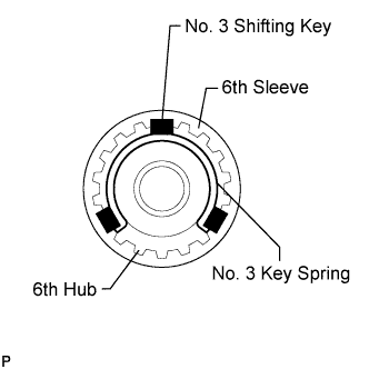
Securely install the 3 No. 3 synchromesh shifting keys into the grooves on the No. 1 synchronizer ring.
-
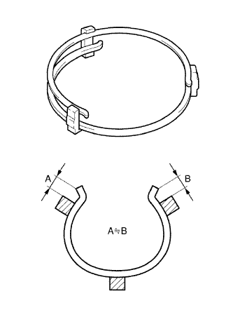
Install the 2 No. 3 synchromesh shifting key springs to the No. 3 synchromesh shifting keys.
Note
-
When installing the No. 3 synchromesh shifting key springs, leave an equal amount of excess space at both ends of each spring to prevent interference with the inside of the clutch hub.
-
Do not allow the openings of the No. 3 synchromesh shifting key springs to overlap.
-
-
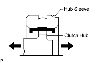
Check that the clutch hub and hub sleeve slide smoothly.
-
-
INSTALL STOPPER PLATE 6TH
-
Install a new stopper plate 6th to the 6th sleeve and hub assembly.
-
-
INSTALL COUNTER GEAR 6TH
-
Apply engine oil to the radial ball bearing and the inside of the No. 1 synchronizer ring.
-
Install the counter gear 6th, radial ball bearing, and No. 1 synchronizer ring.
-
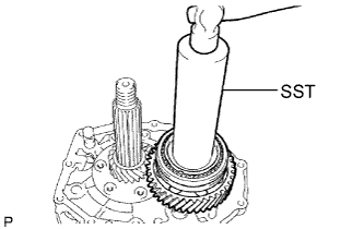
Align the No. 1 synchronizer ring with the groove on the 6th sleeve and hub assembly. Using SST and a hammer, install the 6th sleeve and hub assembly.
- SST
- 09308-14010
-
Using a snap ring expander, install the shaft snap ring.
-
Select the thickest shaft snap ring that can be installed from the following 3 types.
Thickness mm (in.) Identification Color 1.7 (0.0669) White 1.8 (0.0709) - 1.9 (0.0748) Blue Note
-
If the shaft snap ring is deformed or damaged, replace it with a new one.
-
Check that the snap ring is securely installed.
-
-
-
-
INSTALL NO. 4 GEAR SHIFT FORK SHAFT
-
Apply engine oil to the No. 4 gear shift fork shaft installation hole on the manual transmission case.
-
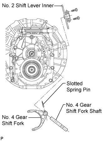
Install the No. 4 gear shift fork and No. 4 gear shift fork shaft.
-
Align the holes for the shift head slotted spring pin and tap in the slotted spring pin using a hammer.
-
-
INSTALL NO. 2 SHIFT LEVER INNER
-
Install the No. 2 shift lever inner with 2 bolts.
- Torque:
- 50 N*m { 510 kgf*cm, 37 ft.*lbf }
-
-
INSTALL TRANSMISSION REAR BEARING RETAINER OIL SEAL
-
Apply MP grease to the inside of the needle bearing and apply engine oil to the needle bearing contact surface of the transmission rear case.
-
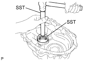
Using SST and a hammer, tap the needle bearing into the transmission rear case from the inside with the inscribed mark facing outward.
- SST
- 09950-60010 ( 09951-00550, 09951-00620, 09952-06010 )
- 09950-70010 ( 09951-07150 )
-
Apply engine oil to the outer circumference of a new transmission rear bearing retainer oil seal.
-
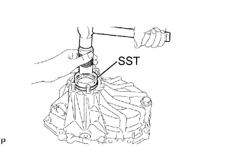
Using SST, install a new transmission rear bearing retainer oil seal to the rear transmission case.
- SST
- 09310-35010
Note
Do not damage the lip of the transmission rear bearing retainer oil seal.
-
Coat the lip of the oil seal with MP grease.
-
-
INSTALL REAR TRANSMISSION CASE
-
Clean the seal packing attached on the manual transmission case and rear transmission case a scraper and wire brush. Then remove the oil with non-residue type solvent or equivalent.
-
Apply FIPG to the manual transmission case as shown in the illustration.
Note
Before applying FIPG, remove any moisture, grease, and oil from the sealing surface. FIPG should be applied in a continuous line (width of 2 mm (0.079 in.) or more).
FIPG Toyota Genuine Seal Packing 1281, Three Bond 1281 or equivalent. -
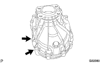
Install the 12 bolts and rear transmission case.
- Torque:
- 46 N*m { 470 kgf*cm, 34 ft.*lbf }
Note
The 2 bolts indicated by the arrows in the illustration are precoated bolts (coated with Loctite). Remove any sealing material from the threads of the transmission case and install new precoated bolts.
-
-
INSTALL NO. 2 CLUTCH HOUSING COVER
-
Clean the seal packing attached on the manual transmission case and No. 2 clutch housing cover a scraper and wire brush. Then remove the oil with non-residue type solvent or equivalent.
-
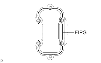
Apply FIPG to the manual transmission case as shown in the illustration.
Note
Before applying FIPG, remove any moisture, grease, and oil from the sealing surface. FIPG should be applied in a continuous line (width of 2 mm (0.079 in.) or more).
FIPG Toyota Genuine Seal Packing 1281, Three Bond 1281 or equivalent. -
Install the 6 bolts and No. 2 clutch housing cover.
-
-
INSTALL MANUAL TRANSMISSION POWER TAKE-OFF COVER
-
Install a new gasket and transmission power take-off cover with 6 new bolts.
- Torque:
- 37 N*m { 380 kgf*cm, 28 ft.*lbf }
Note
The bolts are precoated bolts (coated with Loctite). Remove any sealing material from the threads of the transmission case and install new precoated bolts.
-
-
INSTALL SHIFT LEVER SHAFT HOUSING
-
Clean the seal packing attached on the manual transmission case and shift lever shaft housing a scraper and wire brush. Then remove the oil with non-residue type solvent or equivalent.
-
Move the shift lever to the N position.
-
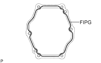
Apply FIPG to the manual transmission case as shown in the illustration.
Note
Before applying FIPG, remove any moisture, grease, and oil from the sealing surface. FIPG should be applied in a continuous line (width of 2 mm (0.079 in.) or more).
FIPG Toyota Genuine Seal Packing 1281, Three Bond 1281 or equivalent. -
Install the transmission oil filter plate and shift lever shaft housing with 6 new bolts.
- Torque:
- 27 N*m { 275 kgf*cm, 20 ft.*lbf }
Note
The bolts are precoated bolts (coated with Loctite). Remove any sealing material from the threads of the transmission case and install new precoated bolts.
-
-
INSTALL DETENT ASSEMBLY
-
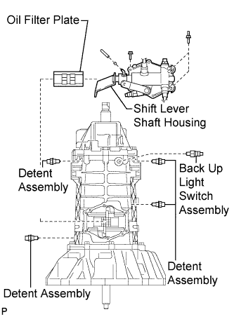
Remove any sealing material from the threads of the detent assembly. Then apply sealant to the threads of the detent assembly.
Sealant Toyota Genuine Loctite 242 or equivalent. -
Install it to the manual transmission case.
- Torque:
- 27 N*m { 275 kgf*cm, 20 ft.*lbf }
-
-
INSTALL BACK UP LIGHT SWITCH ASSEMBLY
-
Apply sealant to the threads of the back up light switch assembly.
Sealant Toyota Genuine Loctite 242 or equivalent. -
Install it to the manual transmission case.
- Torque:
- 39 N*m { 400 kgf*cm, 29 ft.*lbf }
-
-
INSTALL MANUAL TRANSMISSION CASE PLUG
-
Apply engine oil to the O-ring.
-
Install the manual transmission case plug and O-ring.
- Torque:
- 39 N*m { 400 kgf*cm, 29 ft.*lbf }
-