MYY6S MANUAL TRANSMISSION UNIT DISASSEMBLY

Note
-
The transmission case and clutch housing are made of aluminum. Be careful not to damage them.
-
Pay special attention not to damage the ribs of the transmission case and clutch housing. If the ribs are damaged, the strength of the case will be reduced.
-
Use caution when handling heavy parts such a transmission case or gears.
-
REMOVE MANUAL TRANSMISSION CASE PLUG
-
Remove the manual transmission case plug and O-ring.
-
-
REMOVE BACK UP LIGHT SWITCH ASSEMBLY
-
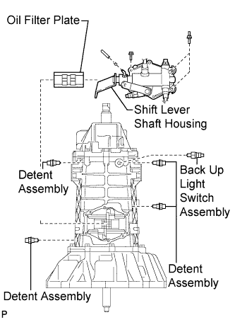
Remove the back up light switch assembly.
-
-
REMOVE DETENT ASSEMBLY
-
Remove the 2 detent assemblies.
-
-
REMOVE SHIFT LEVER SHAFT HOUSING
-
Remove the 6 bolts, shift lever shaft housing and transmission oil filter plate.
-
-
REMOVE MANUAL TRANSMISSION POWER TAKE-OFF COVER
-
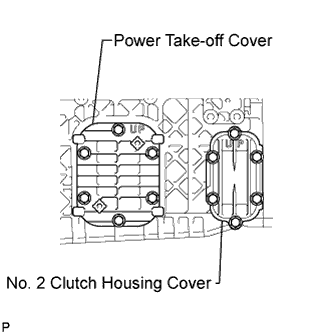
Remove the 6 bolts, manual transmission power take-off cover and gasket.
-
Remove the 6 bolts and No. 2 clutch housing cover.
-
-
REMOVE REAR TRANSMISSION CASE
-
Remove the 12 bolts and rear transmission case.
-
-
REMOVE NEEDLE ROLLER BEARING
-
Using a screwdriver, remove the transmission rear bearing retainer oil seal from the transmission rear case.
Tech Tips
Inspect the transmission rear bearing retainer oil seal. If it is worn or damaged, replace it.
-
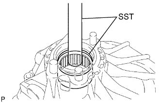
Using SST and a hammer, remove the needle roller bearing from the transmission rear case.
- SST
- 09950-60010 ( 09951-00620 )
- 09950-70010 ( 09951-07150 )
-
-
REMOVE NO. 2 SHIFT LEVER INNER
-
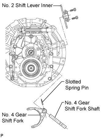
Remove the 2 bolts and No. 2 shift lever inner.
-
-
REMOVE NO. 4 GEAR SHIFT FORK SHAFT
-
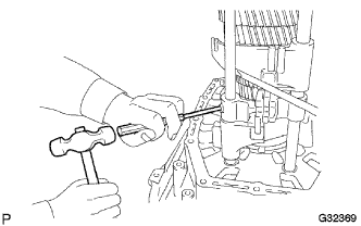
Using a pin punch (5 mm (0.20 in.)) and a hammer, remove the shift head set slotted spring pin and No. 4 gear shift fork shaft from the No. 4 gear shift fork.
-
-
REMOVE COUNTER GEAR 6TH
-
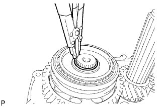
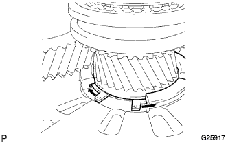
Using a snap ring expander, remove the shaft snap ring.
-
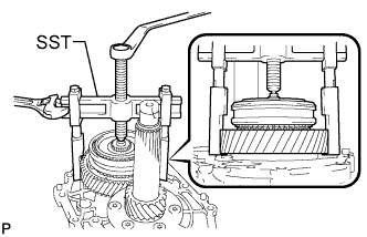
Using SST, remove the 6th sleeve and hub assembly, radial ball bearing and 6th counter gear from the counter gear.
- SST
- 09950-40011 ( 09951-04020, 09952-04010, 09953-04020, 09954-04010, 09955-04031, 09957-04010 )
-
-
REMOVE STOPPER PLATE 6TH
-
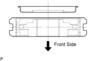
Remove the stopper plate 6th from the 6th sleeve and hub assembly.
Tech Tips
The arrow in the illustration shows the front side of the transmission.
-
-
REMOVE 6TH SLEEVE AND HUB ASSEMBLY
-
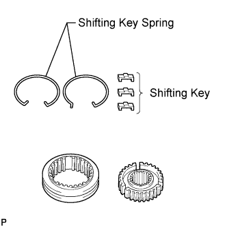
Remove the 2 No. 3 synchromesh shifting key springs, 3 No. 3 synchromesh shifting keys and clutch hub from the hub sleeve.
-
-
REMOVE SPEEDOMETER DRIVE GEAR
-
Remove the speedometer drive gear and speedometer drive gear spacer.
-
-
REMOVE OUTPUT SHAFT REAR BEARING RETAINER
-
Using a "TORX" socket wrench (T50), remove the 10 "TORX" screws and output shaft rear bearing retainer from the manual transmission case.
-
-
REMOVE REVERSE IDLER GEAR SUB-ASSEMBLY
-
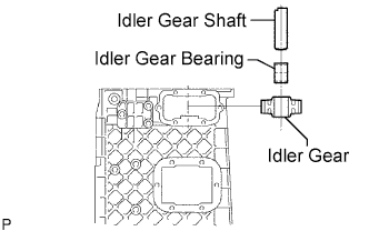
Remove the reverse idler gear shaft, reverse idler gear sub-assembly and reverse idler gear bearing.
-
-
REMOVE OUTPUT SHAFT BEARING SHAFT SNAP RING
-
Using a snap ring expander, remove the output shaft bearing shaft snap ring from the output shaft rear bearing.
-
Remove the gear shaft bearing setting shim.
-
-
REMOVE SNAP RING
-
Using a snap ring expander, remove the snap ring.
-
-
REMOVE MANUAL TRANSMISSION CASE
-
Remove the 13 bolts and manual transmission case from the clutch housing.
-
-
REMOVE COUNTER GEAR REAR BEARING
-
Remove the counter gear rear bearing or roller (outer race) from the manual transmission case.
-
-
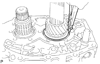
REMOVE NO. 2 GEAR SHIFT FORK SHAFT
-
Using a pin punch (5 mm (0.20 in.)) and hammer, tap out the slotted spring pin.
Note
Place a brass bar on the opposite side of the No. 2 gear shift fork shaft to prevent damage to other parts.
-
Remove the No. 2 gear shift fork shaft and No. 3 gear shift head.
-
-
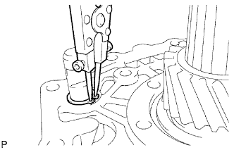
REMOVE NO. 1 GEAR SHIFT FORK SHAFT
-
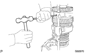
Using a pin punch (5 mm (0.20 in.)) and hammer, tap out the slotted spring pin.
Note
Place a brass bar on the opposite side of the No. 1 gear shift fork shaft to prevent damage to other parts.
-
Remove the No. 1 shift fork shaft, No. 1 gear shift fork, No. 2 gear shift fork and No. 3 gear shift head.
-
-
INSPECT SHIFT ARM BUSHING
-
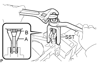
Using SST, remove the shift arm bushing from the No. 3 gear shift fork.
- SST
- 09319-60020
Note
Do not damage the inner surface of the No. 3 gear shift fork.
-
Using SST, remove the shift arm bushing from the No. 2 gear shift fork.
- SST
- 09319-60020
Note
Do not damage the inner surface of the No. 2 gear shift fork.
-
-
REMOVE TRANSMISSION MAGNET
-
Remove the transmission magnet from the clutch housing.
-
-
REMOVE OUTPUT SHAFT ASSEMBLY
-
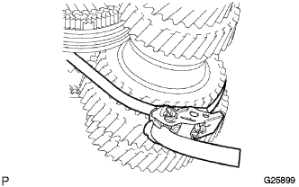
Using 2 straps with a ratcheting function such as tie down straps, securely bind the output shaft assembly, counter gear, and input shaft assembly at 2 places.
-
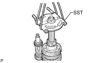
Install SST to the output shaft assembly with the output shaft rear set nut. Hang the assembly with cables.
- SST
- 09950-00020
-
While expanding the front bearing shaft snap ring using a snap ring expander, remove the input shaft assembly, output shaft assembly, and counter gear as a unit from the clutch housing.
-
-
REMOVE CLUTCH HOUSING BUSHING
-
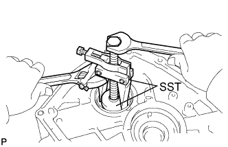
Using SST, remove the clutch housing bushing from the clutch housing.
- SST
- 09319-60020
Note
Do not damage the inner surface of the clutch housing.
Tech Tips
Inspect the clutch housing bushing. If it is worn or damaged, replace it.
-
-
REMOVE COUNTER GEAR FRONT BEARING
-
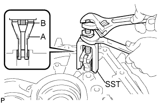
Using SST, remove the counter gear front bearing (outer race) from the clutch housing.
- SST
- 09308-10010
- 09950-60010 ( 09951-00470 )
- 09950-40011 ( 09957-04010 )
Tech Tips
Inspect the counter gear front bearing. If it is worn or damaged, replace it.
-
-
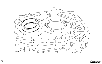
REMOVE TRANSMISSION FRONT BEARING RETAINER OIL SEAL
-
Using a screwdriver, remove the transmission front bearing retainer oil seal from the clutch housing.
Tech Tips
Inspect the transmission front bearing retainer oil seal. If it is worn or damaged, replace it.
-
-
INSPECT GEAR SHIFT FORK
-
Using a micrometer, measure the thickness of the claw part of each gear shift fork.
Standard Inspection Part Standard Thickness (mm) Minimum Thickness (mm) No. 1 gear shift fork 9.60 to 9.85 (0.3780 to 0.3878) 9.0 (0.3543) No. 2 gear shift fork 9.60 to 9.85 (0.3780 to 0.3878) 9.0 (0.3543) No. 3 gear shift fork 9.60 to 9.85 (0.3780 to 0.3878) 9.0 (0.3543) No. 4 gear shift fork 9.60 to 9.85 (0.3780 to 0.3878) 9.3 (0.3661) If the thickness is less than the minimum, replace the gear shift fork.
-
Visually check each gear shift fork.
If any wear, damage, or other problem is found, replace the gear shift fork.
-
Inspect each part of the shift mechanism.
If any damage, bending, or uneven wear is found, replace the part.
-
-
INSPECT NO. 3 SYNCHROMESH SHIFTING KEY
-
Using vernier calipers, measure the clearance between the No. 3 synchromesh shifting key and No. 3 synchronizer ring groove.
Standard clearance 3.46 to 3.76 mm (0.1362 to 0.1480 in.) If the clearance is not within the specified range, replace the No. 3 synchromesh shifting key and No. 3 synchronizer ring.
-