MANUAL TRANSMISSION ASSEMBLY INSTALLATION

-
INSTALL RELEASE FORK SUPPORT
-
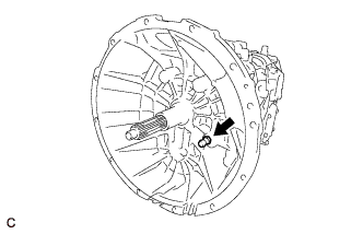
Install the release fork support to the transmission assembly.
- Torque:
- 47 N*m { 480 kgf*cm, 35 ft.*lbf }
-
-
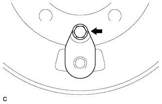
INSTALL CLUTCH RELEASE BEARING ASSEMBLY
-
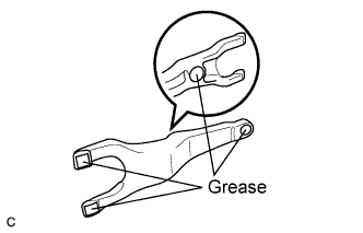
Apply release hub grease to the release fork as shown in the illustration.
Grease Toyota Genuine Release Hub Grease or equivalent -
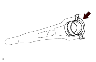
Install the release bearing to the release fork.
-
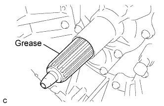
Apply clutch spline grease to the input shaft spline.
Grease Toyota Genuine Clutch Spline Grease or equivalent -
Install the boot.
-
Install the clutch release fork assembly to the transmission assembly.
-
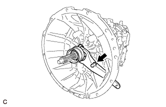
Install the release fork to the release fork support.
Note
After installation, move the fork back and forth to check that the release bearing slides smoothly.
-
-
INSTALL MANUAL TRANSMISSION ASSEMBLY
-
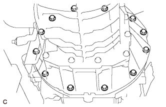
Support the manual transmission with a transmission jack.
-
Install the transmission.
Note
Do not apply excessive force to the transmission assembly as this will cause the input shaft to break.
-
Install the 12 bolts.
- Torque:
- 43 N*m { 440 kgf*cm, 32 ft.*lbf }
-
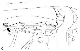
Install the connector and clamp.
-
-
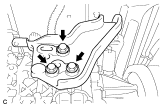
INSTALL NO. 1 ENGINE MOUNTING BRACKET
-
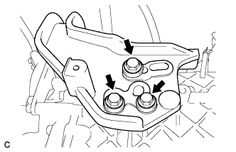
Install the No. 1 engine mounting bracket with the 3 bolts and 3 washers.
- Torque:
- 103 N*m { 1050 kgf*cm, 76 ft.*lbf }
-
Install the nut.
- Torque:
- 64 N*m { 653 kgf*cm, 47 ft.*lbf }
-
-
INSTALL NO. 3 ENGINE MOUNTING BRACKET
-
Install the No. 3 engine mounting bracket with the 3 bolts and 3 washers.
- Torque:
- 103 N*m { 1050 kgf*cm, 76 ft.*lbf }
-
Install the nut.
- Torque:
- 64 N*m { 653 kgf*cm, 47 ft.*lbf }
-
-
INSTALL CLUTCH RELEASE CYLINDER ASSEMBLY
-
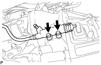
Install the clutch release cylinder assembly with the 2 bolts.
- Torque:
- 12 N*m { 120 kgf*cm, 9 ft.*lbf }
-
-
INSTALL FLOOR SHIFT CABLE TRANSMISSION CONTROL SHIFT
-
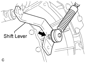
Install the control shift cable to the shift lever with the nut.
- Torque:
- 28 N*m { 280 kgf*cm, 20 ft.*lbf }
-
-
INSTALL FLOOR SHIFT CABLE TRANSMISSION CONTROL SELECT
-
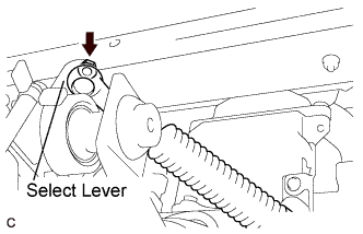
Install the control select cable to the select lever with the nut.
- Torque:
- 28 N*m { 280 kgf*cm, 20 ft.*lbf }
-
-
INSTALL PARKING BRAKE PLATE SUB-ASSEMBLY
-
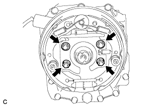
Install the parking brake plate sub-assembly with the 4 nuts.
- Torque:
- 127 N*m { 1290 kgf*cm, 93 ft.*lbf }
-
-
INSTALL PARKING BRAKE DRUM SUB-ASSEMBLY
-
Install the companion flange.
-
Install the parking brake dust cover to the parking drum sub-assembly with the bolt.
- Torque:
- 8.2 N*m { 84 kgf*cm, 73 in.*lbf }
-
Install the parking drum sub-assembly.
-
-
INSTALL MANUAL TRANSMISSION OUTPUT SHAFT REAR SET NUT
-
Apply engine oil to a new O-ring, and install it to the companion flange.
-
Pull the parking brake lever fully, and shift into the 1st position.
-
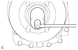
Using a 36 mm socket wrench, install a new transmission output shaft rear set nut.
- Torque:
- 289 N*m { 2947 kgf*cm, 213 ft.*lbf }
-
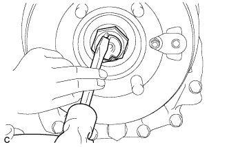
Using a chisel and hammer, stake the transmission output shaft rear set nut.
-
-
INSTALL PROPELLER SHAFT ASSEMBLY
-
INSTALL NO. 1 EXHAUST PIPE SUPPORT BRACKET
-
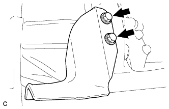
Install the No. 1 exhaust pipe support bracket with the 2 bolts.
- Torque:
- 50 N*m { 510 kgf*cm, 37 ft.*lbf }
-
-
INSTALL EXHAUST FRONT PIPE ASSEMBLY
-
Install a new gasket and the front exhaust pipe assembly, and temporarily tighten 3 new nuts.
-
Temporarily tighten a new bolt.
-
Tighten the 3 nuts.
- Torque:
- 70 N*m { 714 kgf*cm, 52 ft.*lbf }
-
Tighten the bolt.
- Torque:
- 25 N*m { 250 kgf*cm, 18 ft.*lbf }
-
-
INSTALL EXHAUST RETARDER ASSEMBLY
-
Install 2 new gaskets and exhaust retarder assembly with 4 new bolts.
- Torque:
- 30 N*m { 306 kgf*cm, 22 ft.*lbf }
-
Connect the vacuum hose.
-
-
CONNECT CABLE TO NEGATIVE BATTERY TERMINAL
-
INSPECT AND ADJUST MANUAL TRANSMISSION OIL
-
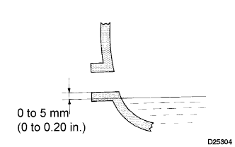
Park the vehicle in a level place.
-
Remove the transmission filler plug and gasket.
-
Check that the oil surface is within 5 mm (0.20 in.) below the lowest point of the transmission filler plug opening.
Oil grade API CD, CE, CF, CH-4 or CL-4 Viscosity SAE 10W-30 or 10W-40 Note
-
Problems may occur when the oil level is too high or too low.
-
After replacing the oil, drive the vehicle and check the oil level again.
-
-
Check for oil leaks if the oil level is low.
-
Install the transmission filler plug and a new gasket.
- Torque:
- 39 N*m { 400 kgf*cm, 29 ft.*lbf }
-
-
INSPECT FOR EXHAUST GAS LEAK