MANUAL TRANSMISSION ASSEMBLY REMOVAL

-
DISCONNECT CABLE FROM NEGATIVE BATTERY TERMINAL
-
REMOVE EXHAUST RETARDER ASSEMBLY
-
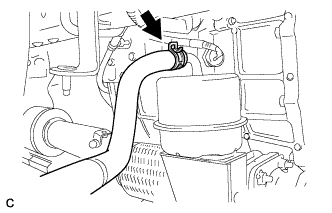
Disconnect the vacuum hose.
-
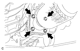
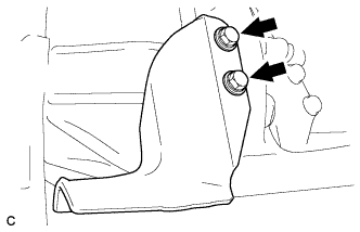
Remove the 4 bolts and exhaust retarder assembly.
-
Remove the 2 gaskets from the exhaust retarder assembly.
-
-
REMOVE EXHAUST FRONT PIPE ASSEMBLY
-
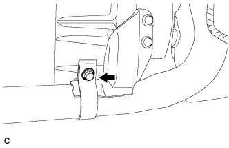
Remove the bolt.
-
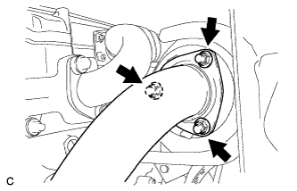
Remove the 3 nuts and front exhaust pipe assembly.
-
Remove the gasket.
-
-
REMOVE NO. 1 EXHAUST PIPE SUPPORT BRACKET
-
Remove the 2 bolts and No. 1 exhaust pipe support bracket.
-
-
REMOVE PROPELLER SHAFT ASSEMBLY
-
REMOVE MANUAL TRANSMISSION OUTPUT SHAFT REAR SET NUT
-
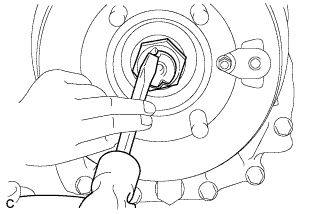
Using a chisel and a hammer, release the staked part of the transmission output shaft rear set nut.
-
Pull the parking brake lever fully, and shift into the reverse position.
-
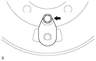
Using a 36 mm socket wrench, remove the transmission output shaft rear set nut.
-
Using a screwdriver, remove the O-ring.
-
-
REMOVE PARKING BRAKE DRUM SUB-ASSEMBLY
-
Remove the bolt and dust cover from the parking brake drum.
-
Release the parking brake lever.
-
Remove the parking brake drum sub-assembly and companion flange.
-
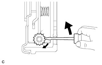
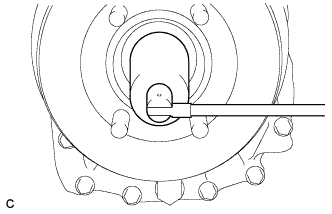
If the brake drum cannot be removed easily, turn the shoe adjuster in the direction of the illustrated arrow mark until the drum turns freely.
-
-
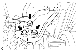
SEPARATE PARKING BRAKE PLATE SUB-ASSEMBLY
-
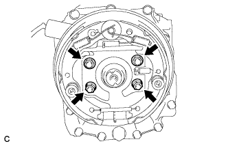
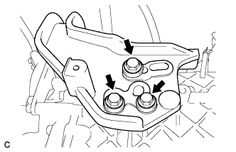
Remove the 4 nuts and disconnect the parking brake plate sub-assembly.
Tech Tips
Use wire or an equivalent tool to keep the parking brake plate sub-assembly from hanging down by the parking brake cable.
-
-
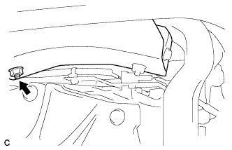
DISCONNECT FLOOR SHIFT CABLE TRANSMISSION CONTROL SELECT
-
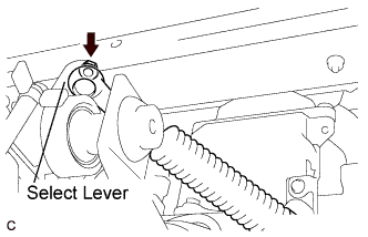
Remove the nut and control select cable from the select lever.
-
-
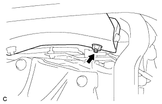
DISCONNECT FLOOR SHIFT CABLE TRANSMISSION CONTROL SHIFT
-
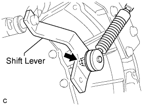
Remove the nut and control shift cable from the shift lever.
-
-
SEPARATE CLUTCH RELEASE CYLINDER ASSEMBLY
-
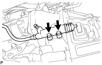
Remove the 2 bolts and disconnect the clutch release cylinder.
-
-
SUPPORT TRANSMISSION ASSEMBLY
-
Support the transmission assembly with a transmission jack.
-
-
DISCONNECT NO. 3 ENGINE MOUNTING BRACKET
-
Remove the nut.
-
Remove the 3 bolts and 3 washers and disconnect the No. 3 engine mounting bracket.
-
-
DISCONNECT NO. 1 ENGINE MOUNTING BRACKET
-
Remove the nut.
-
Remove the 3 bolts and 3 washers and disconnect the No. 1 engine mounting bracket.
-
-
SUPPORT ENGINE ASSEMBLY
-
Support the engine assembly with a transmission jack.
Note
Do not tilt the engine and transmission assembly more than necessary.
-
-
REMOVE MANUAL TRANSMISSION ASSEMBLY
-
Disconnect the connector and clamp.
-
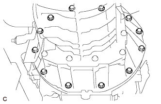
Remove the 12 bolts.
-
Remove the transmission assembly.
Note
Do not apply excessive force to the transmission assembly as this will cause the input shaft to break.
-
-
REMOVE CLUTCH RELEASE BEARING ASSEMBLY
-
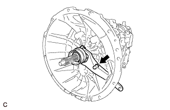
Separate the clutch release fork from the release fork support.
-
Remove the clutch release fork with the clutch release bearing assembly from the transmission assembly.
-
Remove the boot.
-
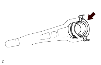
Disconnect the release bearing assembly from the release fork.
-
-
REMOVE RELEASE FORK SUPPORT
-
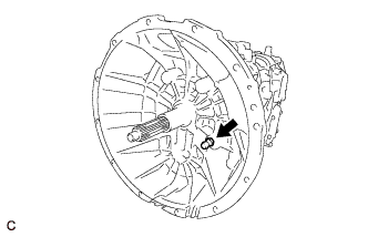
Remove the release fork support.
-