SPEEDOMETER SENSOR INSTALLATION

-
INSTALL SPEEDOMETER DRIVEN (MTM) GEAR SUB-ASSEMBLY
-
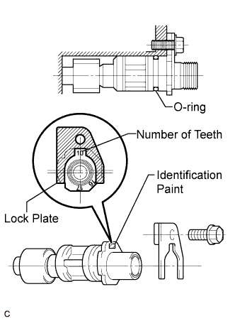
Coat the O-ring with engine oil.
-
Positioning the paint number of teeth and the lock plate as shown in the illustration, install the speedometer driven gear with the bolt.
- Torque:
- 19 N*m { 196 kgf*cm, 14 ft.*lbf }
Note
-
If the identification paint cannot be identified, refer to the identification groove on the gear and the table above to determine the number of teeth and position the appropriate number of teeth as shown in the illustration when installing the speedometer driven gear.
-
Make sure that the number of teeth can be seen after installing the gear.
-
Connect the connector.
-