PROPELLER SHAFT ASSEMBLY REASSEMBLY

Note
-
When using a vise, place aluminum plates between the part and vise.
-
When using a vise, do not overtighten it.
-
INSTALL SPIDER BEARING
-
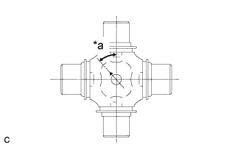
Text in Illustration *a 45° Install the grease fitting onto the spider section.
- Torque:
- 6.4 N*m { 65 kgf*cm, 57 in.*lbf }
Note
Install the grease fitting so that the hole is oriented as shown in the illustration.
-
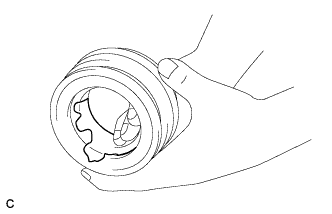
Apply a sufficient amount of MP grease to the spider journal section.
-
Remove the old grease in the bearing case and needle roller and apply a sufficient amount of MP grease.
-
Apply MP grease to the bearing case lip.
-
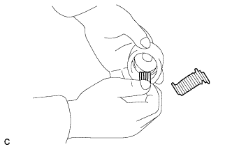
Insert the needle roller into the bearing case.
-
Install the 4 spider bearings to the universal joint spider assembly.
-
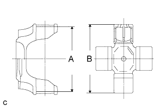
Measure the size of groove A of the rear propeller shaft joint spider bearing snap ring of the universal joint sleeve yoke.
-
After inserting the spider bearing into the spider journal section, measure the size of universal joint B.
Tech Tips
Size B should be measured with the universal joint fixed in a vise because the universal joint spider assembly and spider bearing will become stuck.
-
Text in Illustration *a Identification Paint Select the thickness of the rear propeller shaft joint spider bearing snap ring that makes sizes A and B equal.
Snap Ring Thickness: Part No. Thickness mm (in.) Identification (Color) 90035-21044 1.50 (0.0591) White 90035-21043 1.53 (0.0602) Red 90035-21042 1.56 (0.0614) Green 90035-21041 1.59 (0.0626) Blue 90035-21040 1.62 (0.0638) Yellow 90035-21039 1.65 (0.0650) Pink 90035-21038 1.68 (0.0661) Orange -
Remove the 4 spider bearings from the universal joint spider assembly.
-
-
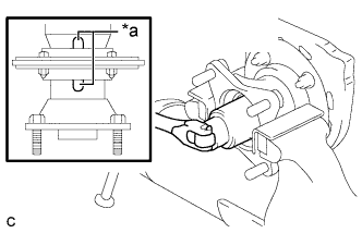
INSTALL UNIVERSAL JOINT SPIDER ASSEMBLY
-
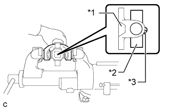
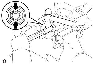
Text in Illustration *1 Flange yoke *2 Universal joint spider assembly *3 Grease fitting Insert the universal joint spider assembly into the flange yoke. Using a vise, press the spider bearing into the end of the rear propeller shaft joint spider bearing snap ring.
Note
-
Be sure the spider bearing is inserted in the proper direction.
-
Do not insert the spider bearing at an angle.
-
Do not damage the rib of the spider bearing.
Tech Tips
Insert the spider bearing until it reaches the bottom of the groove where the rear propeller shaft joint spider bearing snap ring is installed.
-
-
Press in the spider bearing on the other side using the same procedure.
-
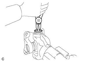
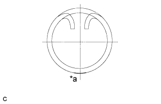
Using snap ring pliers, install the rear propeller shaft joint spider bearing snap ring.
-
-
INSPECT UNIVERSAL JOINT FLANGE
-
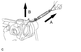
Insert the hook of a spring tension gauge into a bolt hole in the flange yoke and measure the rotating torque.
- Torque:
- Standard rotating torque (at starting)
- 0.8 to 2.9 N*m { 9 to 29 kgf*cm, 8 to 25 in.*lbf }
Note
Measure the rotating torque of the universal joint in two directions, A and B, on the flange yoke side.
-
Text in Illustration *a Identification Paint When the rotating torque is less than the standard, use a thicker rear propeller shaft joint spider bearing snap ring, and when it is greater, use a thinner rear propeller shaft joint spider bearing snap ring.
Snap Ring Thickness: Part No. Thickness mm (in.) Identification (Color) 90035-21044 1.50 (0.0591) White 90035-21043 1.53 (0.0602) Red 90035-21042 1.56 (0.0614) Green 90035-21041 1.59 (0.0626) Blue 90035-21040 1.62 (0.0638) Yellow 90035-21039 1.65 (0.0650) Pink 90035-21038 1.68 (0.0661) Orange
-
-
INSTALL DUST SEAL
-
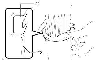
Text in Illustration *1 Dust seal *2 Dust cover Install a new dust seal to the universal joint sleeve yoke.
Note
-
Install the dust seal so that the lip faces outwards.
-
After installation, check that the outside of the dust seal contacts the dust cover.
-
-
Apply MP grease to the dust seal lip.
-
-
INSTALL UNIVERSAL JOINT SLEEVE YOKE SUB-ASSEMBLY
-
Remove the old grease from the spline and sliding sections.
-
Remove the rust and dirt from the spline sections.
-
Apply MP grease to the spline and sliding sections.
-
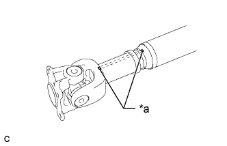
Text in Illustration *a Matchmark Align the matchmarks of the sliding yoke and universal joint sleeve yoke, and insert the universal joint sleeve yoke.
Note
Phase marks are imprinted on each yoke. Install the universal joint sleeve yoke so that the matchmarks of the sliding yoke and universal joint sleeve yoke are aligned.
-
Install the grease fitting.
- Torque:
- 6.4 N*m { 65 kgf*cm, 57 in.*lbf }
-
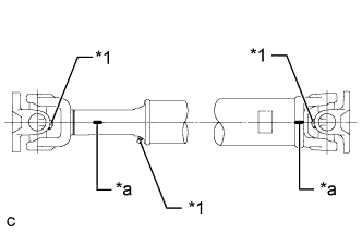
Text in Illustration *1 Grease fitting *a Phase mark Check that the directions of the phase marks and grease fitting of each joint are as shown in the illustration.
-
-
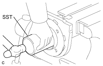
INSTALL PROPELLER SHAFT DUST DEFLECTOR
-
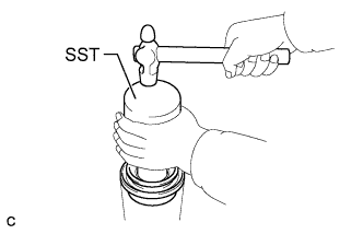
Using SST and a hammer, tap a new No. 1 propeller shaft dust deflector into the propeller intermediate shaft assembly.
- SST
- 09316-12010
Note
Do not deform the No. 1 propeller shaft dust deflector.
-
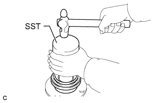
Using SST and a hammer, tap a new No. 5 propeller shaft dust deflector into the universal joint flange sub-assembly.
- SST
- 09309-37010
- 09316-12010
- 09710-28021 ( 09710-08031 )
Note
Do not deform the No. 5 propeller shaft dust deflector.
-
-
INSTALL CENTER NO. 1 SUPPORT BEARING ASSEMBLY
-
Apply MP grease to the inside of the center No. 1 support bearing.
-
Install the center No. 1 support bearing plate to the propeller intermediate shaft assembly.
-
Using SST and a hammer, tap in the center No. 1 support bearing.
- SST
- 09309-60010
Note
When driving in the center No. 1 support bearing, pay attention not to damage it.
-
Install the center No. 1 support bearing cushion sub-assembly, 4 collars and center No. 1 support bearing plate.
-
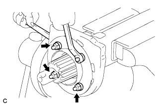
Secure the bolt and install the 4 nuts.
- Torque:
- 27 N*m { 270 kgf*cm, 20 ft.*lbf }
-
-
INSTALL UNIVERSAL JOINT FLANGE SUB-ASSEMBLY
-
Install the grease fitting.
- Torque:
- 6.4 N*m { 65 kgf*cm, 57 in.*lbf }
Note
Install the grease fitting so that the hole is facing the rear of the vehicle.
-
Text in Illustration *a Matchmark Align the matchmarks on the universal joint flange and intermediate shaft flange to install the universal joint flange sub-assembly.
-
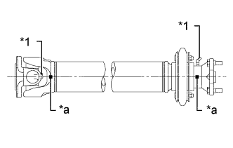
Text in Illustration *1 Grease fitting *a Phase mark Check that the directions of the phase marks and grease fittings of the universal joint flange sub-assembly and propeller intermediate shaft assembly are as shown in the illustration.
-
Using a 41 mm deep socket wrench, install a new lock nut.
- Torque:
- 687 N*m { 7000 kgf*cm, 506 ft.*lbf }
-
Using a chisel and hammer, stake the lock nut.
Note
Stake the lock nut in 2 locations aligned with the cutouts of the shaft shown in the illustration.
-