PROPELLER SHAFT ASSEMBLY DISASSEMBLY

Note
-
When using a vise, place aluminum plates between the part and vise.
-
When using a vise, do not overtighten it.
-
REMOVE UNIVERSAL JOINT SLEEVE YOKE SUB-ASSEMBLY
-
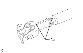
Text in Illustration *a Matchmark Place matchmarks on the universal joint sleeve yoke and sliding yoke.
-
Remove the universal joint sleeve yoke assembly from the sliding yoke.
-
Remove the grease fitting.
-
-
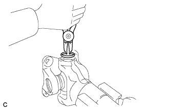
REMOVE DUST SEAL
-
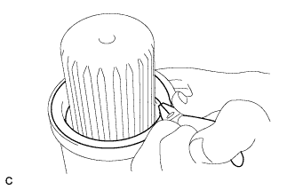
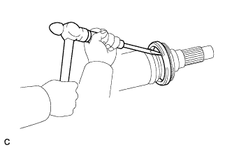
Grip the lip of the dust seal with pliers, and pull up the dust seal.
-
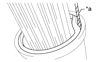
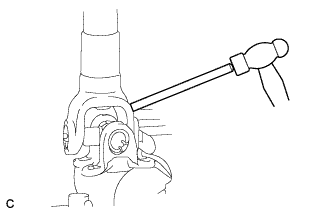
Text in Illustration *a Protective Tape Using a screwdriver remove the dust seal.
Note
-
Do not damage the spline.
-
Do not deform the universal joint sleeve yoke.
-
Replace the propeller shaft assembly if the universal joint sleeve yoke is deformed.
Tech Tips
Tape the screwdriver tip before use.
-
-
-
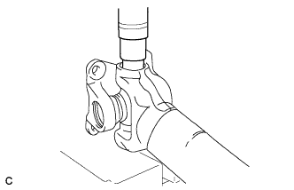
REMOVE SPIDER BEARING
Tech Tips
Use the same procedure for all universal joint spiders.
-
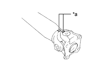
Text in Illustration *a Matchmark Place matchmarks on the flange yoke and sliding yoke.
-
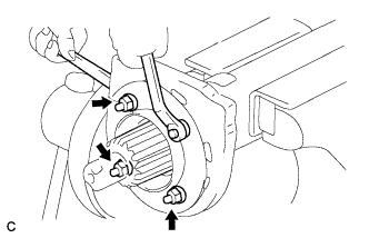
Using snap ring pliers, remove the 2 rear propeller shaft joint spider bearing snap rings.
-
Using a press, press out the spider bearing.
Tech Tips
Press out the bearing until immediately before the universal joint spider assembly contacts the flange yoke.
-
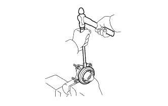
Fix the spider bearing in a vise between aluminum plates.
-
Using a brass bar and hammer, tap on the yoke of the sliding yoke and remove the spider bearing.
-
Remove the spider bearing on the other side using the same procedure.
-
Remove the universal joint spider assembly.
-
Remove the grease fitting.
-
-
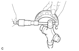
INSPECT UNIVERSAL JOINT SLEEVE YOKE
-
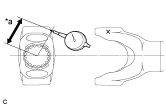
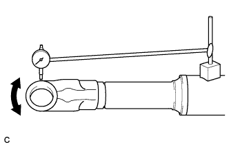
Fixing the sliding yoke horizontally in a vise, place a dial indicator onto the yoke of the universal joint sleeve yoke to measure the free play.
Text in Illustration *a 50 mm (1.97 in.) Tech Tips
Place the dial indicator at a spot 50 mm (1.97 in.) away from the center of the universal joint sleeve yoke.
Standard free play 0.185 to 0.393 mm (0.0073 to 0.0154 in.) Maximum free play 0.63 mm (0.0248 in.) If the free play is more than the maximum, replace the propeller shaft assembly.
-
-
INSPECT SPIDER BEARING
-
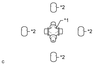
Text in Illustration *1 Universal joint spider assembly *2 Spider bearing Check the universal joint spider assembly and spider bearing for wear or damage.
If there are any scratches or cracks in the spider journal area or on the spider bearing, replace the universal joint spider assembly or spider bearing.
-
Measure the clearance of the spider bearing.
-
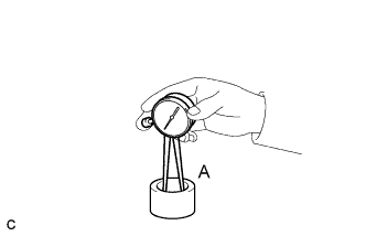
Using a caliper gauge, measure the bore diameter A of the bearing case of the spider bearing.
-
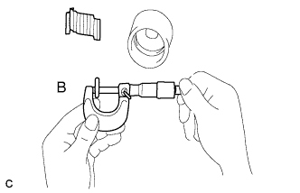
Using a micrometer, measure diameter B of the needle roller.
-
Using a micrometer, measure diameter C of the journal of the universal joint spider assembly.
-
-
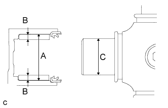
Calculate the clearance between the spider journal and spider bearing as follows: Subtract twice the outside diameter (B x 2) of the needle roller from inside diameter A of the bearing case, and then subtract the result from outside diameter C of the spider journal.
Standard clearance 0.022 to 0.061 mm (0.0009 to 0.0024 in.) Maximum clearance 0.1 mm (0.0039 in.) If the clearance is more than the maximum, replace the universal joint spider assembly and spider bearing.
-
-
REMOVE UNIVERSAL JOINT FLANGE SUB-ASSEMBLY
-
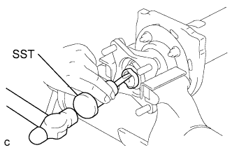
Using SST and a hammer, loosen the staked part of the lock nut.
- SST
- 09930-00010
Note
-
Be sure to use SST with the tapered surface facing the shaft.
-
Do not grind the tip of SST with a grinder or other device.
-
Completely loosen the staked part of the lock nut when removing it.
-
The lock nut is staked in 2 locations.
-
Do not damage the threads of the shaft.
-
Text in Illustration *a Matchmark Place matchmarks on the intermediate shaft flange and universal joint flange.
-
Using a 41 mm deep socket wrench, remove the lock nut and universal joint flange sub-assembly from the propeller intermediate shaft assembly.
Note
Check that the staked nut is released completely before removing the parts as the shaft can be damaged.
-
Remove the grease fitting.
-
-
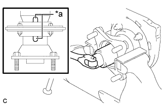
REMOVE CENTER NO. 1 SUPPORT BEARING ASSEMBLY
-
Secure the bolts, remove the 4 nuts respectively, and then remove the center No. 1 support bearing plate, 4 collars and center No. 1 support bearing cushion sub-assembly.
-
Using a brass bar and hammer, tap evenly around the outside of the center No. 1 support bearing to remove it.
-
Remove the center No. 1 support bearing plate.
-
-
REMOVE PROPELLER SHAFT DUST DEFLECTOR
-
Using a screwdriver and hammer, tap out the No. 5 propeller shaft dust deflector from the universal joint flange sub-assembly.
-
Using a screwdriver and hammer, tap out the No. 1 propeller shaft dust deflector from the propeller intermediate shaft assembly.
-