CLUTCH MASTER CYLINDER INSTALLATION

-
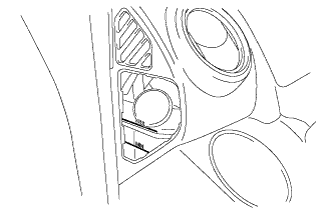
INSTALL CLUTCH MASTER CYLINDER ASSEMBLY
-
Install the clutch master cylinder assembly with the 2 nuts.
- Torque:
- 13 N*m { 130 kgf*cm, 9 ft.*lbf }
-
-
CONNECT CLUTCH RESERVOIR TUBE
-
Slide the clip and connect the clutch reservoir tube.
-
-
CONNECT FLEXIBLE HOSE TO FLEXIBLE HOSE TUBE
-
Using a 12 mm union nut wrench, connect the flexible hose to flexible hose tube.
- Torque:
- 24 N*m { 245 kgf*cm, 18 ft.*lbf }
Note
Use the formula to calculate special torque values for situations where a union nut wrench is combined with a torque wrench Click here
-
-
FILL RESERVOIR WITH BRAKE FLUID
-
Fill the reservoir with brake fluid.
Fluid SAE J1703 or FMVSS No. 116 DOT 3 Note
Add brake fluid to keep the level between the MIN and MAX lines of the reservoir while bleeding the brakes.
-
-
BLEED CLUTCH MASTER CYLINDER
Note
Immediately wash off any brake fluid that comes into contact with any painted surfaces.
Tech Tips
If the clutch master cylinder has been disassembled or if the reservoir becomes empty, bleed the air from the master cylinder.
-
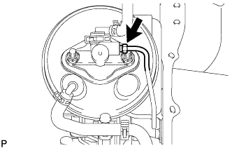
Using a 12 mm union nut wrench, disconnect the flexible hose to flexible hose tube from the clutch master cylinder assembly.
-
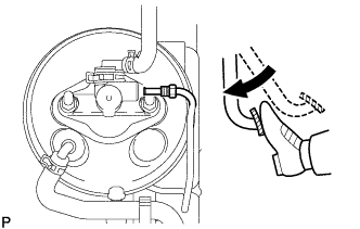
Slowly depress the clutch pedal and hold it down. (Step A).
-
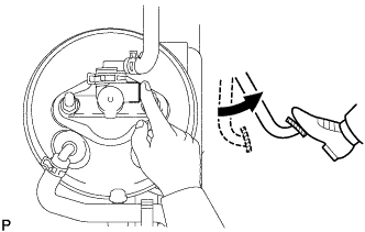
Block the outer holes with your fingers, and release the clutch pedal (Step B).
-
Repeat steps A and B 3 or 4 times.
-
Using a 12 mm union nut wrench, connect the flexible hose to flexible hose tube to the clutch master cylinder assembly.
- Torque:
- 24 N*m { 245 kgf*cm, 18 ft.*lbf }
Note
Use the formula to calculate special torque values for situations where a union nut wrench is combined with a torque wrench Click here.
-
-
INSPECT FOR FLUID LEAK
-
INSPECT FLUID LEVEL IN RESERVOIR
-
Check the fluid level and add fluid if necessary.
Fluid SAE J1703 or FMVSS No. 116 DOT 3
-
-
INSTALL INSTRUMENT PANEL FINISH PANEL SUB-ASSEMBLY LOWER RH
-
Connect each connector.
-
Attach the 3 clips to install the lower instrument panel finish panel sub-assembly LH.
-
Install the 2 clips.
-