CLUTCH PEDAL INSTALLATION

-
INSTALL CLUTCH PEDAL PAD
-
Install the clutch pedal pad to the clutch pedal sub-assembly.
-
-
INSTALL NO. 2 CLUTCH PEDAL CUSHION
-
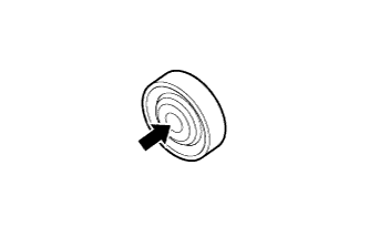
Apply MP grease to the inner surface of a new No. 2 clutch pedal cushion.
Text in Illustration 
MP grease Note
Do not allow grease to adhere to the rubber part of the No. 2 clutch pedal cushion.
-
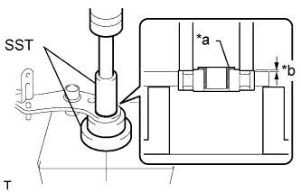
Text in Illustration *a Flange of Bush *b 1.0 mm (0.0394 in.) Using SST and a press, install the No. 2 clutch pedal cushion to the clutch pedal sub-assembly.
Tech Tips
Check that the outer casing of the No. 2 clutch pedal cushion is positioned as shown in the illustration
- SST
- 09316-60011 ( 09316-00061 )
- 09623-30011
Tech Tips
Install the No. 2 clutch pedal cushion so that the flange of the bush is facing the left side of the vehicle.
-
-
INSTALL NO. 1 CLUTCH PEDAL CUSHION
-
Install the 3 No. 1 clutch pedal cushions to the clutch pedal sub-assembly.
-
-
INSTALL CLUTCH PEDAL SHAFT COLLAR
-
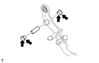
Apply MP grease to both sides of 2 new clutch pedal bushes.
Text in Illustration MP grease -
Install the 2 clutch pedal bushes and clutch pedal shaft collar to the clutch pedal sub-assembly.
-
-
INSTALL CLUTCH PEDAL SPRING
-
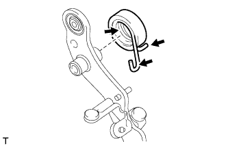
Apply MP grease to the inner surface and hook of the clutch pedal spring.
Text in Illustration MP grease -
Install the clutch pedal spring to the clutch pedal sub-assembly.
-
-
INSTALL CLUTCH PEDAL SUB-ASSEMBLY
-
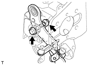
Install the clutch pedal sub-assembly to the clutch pedal bracket sub-assembly with the bolt and nut.
- Torque:
- 35 N*m { 357 kgf*cm, 26 ft.*lbf }
Note
Turn the nut while holding the bolt.
-
Connect the clutch pedal spring to the clutch pedal bracket sub-assembly.
-
-
INSTALL CLUTCH PEDAL STOPPER BOLT
-
Install the clutch pedal stopper bolt to the clutch pedal bracket sub-assembly and temporarily install the lock nut.
Tech Tips
Tighten the lock nut to the specified torque when adjusting the clutch pedal.
-
-
INSTALL CLUTCH PEDAL STROKE SENSOR ASSEMBLY
-
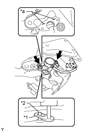
Text in Illustration *1 Arm *2 Rod *a Alignment Mark Insert the clutch pedal rod into the clutch pedal stroke sensor assembly.
-
Align the clutch pedal stroke sensor assembly with the alignment marks on the clutch pedal bracket.
-
Attach the clamp and install the clutch pedal stroke sensor assembly with the 2 nuts.
- Torque:
- 8.5 N*m { 87 kgf*cm, 75 in.*lbf }
-
-
INSTALL CLUTCH WITH AIR CLEANER BOOSTER ASSEMBLY
-
Install the clutch with air cleaner booster assembly to the clutch pedal bracket sub-assembly with the 4 nuts.
- Torque:
- 13 N*m { 130 kgf*cm, 9 ft.*lbf }
-
-
INSTALL CLUTCH MASTER CYLINDER PUSH ROD CLEVIS
-
Install a new clip, hole pin and clutch master cylinder push rod clevis to the clutch with air cleaner booster assembly.
-
-
INSTALL CLUTCH PEDAL BRACKET SUB-ASSEMBLY
-
Install the clutch pedal bracket sub-assembly to the pedal bracket sub-assembly with the 4 bolts.
- Torque:
- 19 N*m { 194 kgf*cm, 14 ft.*lbf }
-
-
INSTALL CLAMP
-
Install the 2 clamps.
-
-
INSTALL PEDAL BRACKET ASSEMBLY
-
CONNECT WIRE HARNESS CONNECTOR
-
Connect the clutch pedal stroke sensor connector.
-
-
INSTALL NO. 1 CLUTCH BOOSTER VACUUM HOSE
-
Install the No. 1 clutch booster vacuum hose with the 2 clamps.
-
Connect the No. 1 clutch booster vacuum hose, and slide the 2 clamps to secure it.
-
-
INSTALL INSTRUMENT PANEL SUB-ASSEMBLY
-
INSTALL CLUTCH MASTER CYLINDER ASSEMBLY
-
FILL RESERVOIR WITH BRAKE FLUID
-
Fill the reservoir with brake fluid.
Fluid SAE J1703 or FMVSS No. 116 DOT 3 Note
Add brake fluid to keep the level between the MIN and MAX lines of the reservoir while bleeding the brakes.
-
-
BLEED CLUTCH LINE
Tech Tips
See Pub. No. RM1008E, page 42-2.
-
INSPECT FOR FLUID LEAK
-
INSPECT FLUID LEVEL IN RESERVOIR
-
Check the fluid level and add fluid if necessary.
Fluid SAE J1703 or FMVSS No. 116 DOT 3
-
-
INSPECT AND ADJUST CLUTCH PEDAL SUB-ASSEMBLY
-
INSTALL EXHAUST RETARDER SWITCH ASSEMBLY
-
Temporarily install the exhaust retarder switch assembly to the clutch pedal bracket sub-assembly with the nut.
Tech Tips
Perform the clutch pedal adjustment after installing the exhaust retarder switch assembly.
-
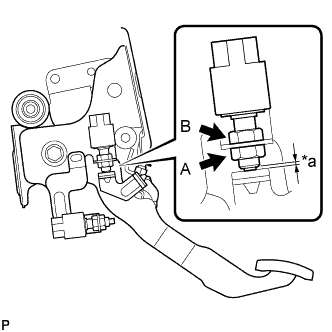
Text in Illustration *a Clearance Without depressing the clutch pedal, turn nut A and nut B as necessary to adjust the clearance shown in the illustration until it is within the specified range.
Standard clearance 0 to 1.0 mm (0 to 0.0393 in.) -
Tighten nut A.
- Torque:
- 24 N*m { 245 kgf*cm, 18 ft.*lbf }
-
Connect the exhaust retarder switch connector.
-
-
INSTALL POWER TAKE-OFF CLUTCH SWITCH ASSEMBLY
-
Temporarily install the power take-off clutch switch assembly to the clutch pedal bracket sub-assembly with the nut.
Tech Tips
Perform the clutch pedal adjustment after installing the power take-off clutch switch assembly.
-
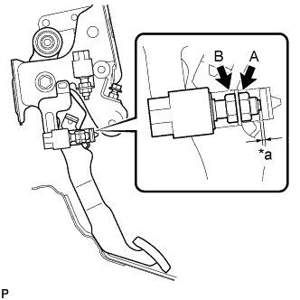
Text in Illustration *a Clearance While depressing the clutch pedal, turn nut A and nut B as necessary to adjust the clearance shown in the illustration until it is within the specified range.
Standard clearance 1.0 to 3.0 mm (0.0394 to 0.118 in.) -
Tighten nut A.
- Torque:
- 24 N*m { 245 kgf*cm, 18 ft.*lbf }
-
Connect the power take-off clutch switch connector.
-
-
CLUTCH PEDAL STROKE SENSOR ZERO POINT CALIBRATION
-
If the clutch pedal stroke sensor has been replaced, perform clutch pedal stroke sensor zero point calibration and release position calibration Click here.
-