GENERATOR (for 60A Type) INSPECTION

-
INSPECT GENERATOR ROTOR ASSEMBLY
-
Check the generator rotor assembly for an open circuit.
-
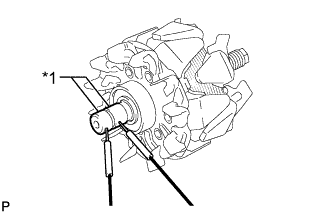
Text in Illustration *1 Slip Ring Measure the resistance according to the value(s) in the table below.
Standard Resistance Tester Connection Condition Specified Condition Slip ring - Slip ring 20°C (68°F) 10.6 to 11.4 Ω If the result is not as specified, replace the generator rotor assembly.
-
-
Check the generator rotor assembly for a short to ground.
-
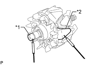
Text in Illustration *1 Slip Ring *2 Rotor Core Measure the resistance according to the value(s) in the table below.
Standard Resistance Tester Connection Condition Specified Condition Slip ring - Rotor core Always 10 kΩ or higher If the result is not as specified, replace the generator rotor assembly.
-
-
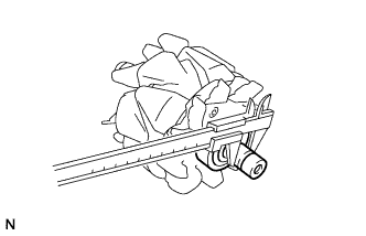
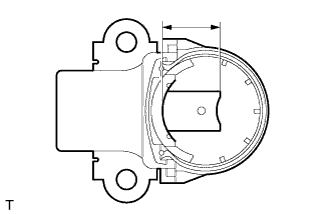
Using a vernier caliper, measure the slip ring diameter.
Standard diameter 14.2 to 14.4 mm (0.559 to 0.567 in.) Minimum diameter 14.0 mm (0.551 in.) If the diameter is less than the minimum, replace the generator rotor assembly.
-
Check that each slip ring is not rough or scorched.
If rough or scorched, restore them with sandpaper (No. 400) or replace the generator rotor assembly.
-
-
INSPECT GENERATOR HOLDER WITH RECTIFIER
-
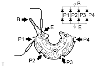
Check the positive terminal of the generator holder with rectifier.
-
Using an ohmmeter, connect one tester probe to terminal B and the other to terminal P1, P2, P3 and P4.
-
Reverse the polarity of the tester probes and repeat the step above.
-
Measure the resistance and check that one polarity shows a resistance of below 1 Ω and the other shows a resistance of 10 kΩ or higher.
If the result is not as specified, replace the generator holder with rectifier.
-
-
Check the negative terminal of the generator holder with rectifier.
-
Using an ohmmeter, connect one tester probe to terminal E and the other to terminal P1, P2, P3 and P4.
-
Reverse the polarity of the tester probes and repeat the step above.
-
Measure the resistance and check that one polarity shows a resistance of below 1 Ω and the other shows a resistance of 10 kΩ or higher.
If the result is not as specified, replace the generator holder with rectifier.
-
-
-
INSPECT GENERATOR BRUSH HOLDER ASSEMBLY
-
Using a vernier caliper, measure the length of the exposed brushes.
Standard exposed length 9.5 to 11.5 mm (0.374 to 0.453 in.) Minimum exposed length 4.5 mm (0.177 in.) If the exposed length is less than the minimum, replace the generator brush holder assembly.
-
-
INSPECT GENERATOR DRIVE END FRAME ASSEMBLY
-
Inspect the stator for ground.
-
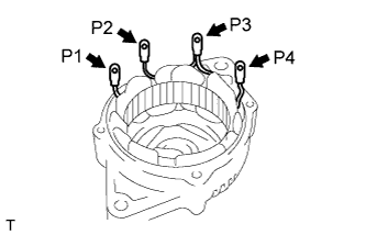
Using an ohmmeter, check the resistance between P1, P2, P4 and generator drive end frame body.
Standard Resistance Tester Connection Condition Specified Condition P1, P2, P4 - generator drive end frame body Always 10 kΩ or higher If the result is not as specified, replace the generator drive end frame assembly.
-
-
Check the stator coil for an open circuit.
-
Using an ohmmeter, check the resistance between P1, P4 and P3.
Standard Resistance Tester Connection Condition Specified Condition P1, P4 - P3 Always 1.5 Ω or less If the result is not as specified, replace the generator drive end frame assembly.
-
-