GENERATOR DISASSEMBLY

-
REMOVE GENERATOR PULLEY
-
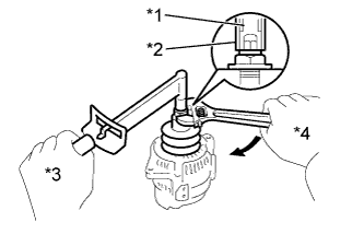
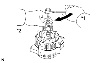
Text in Illustration *1 SST 1-A *2 SST 1-B *3 Hold *4 Turn Hold SST 1-A with a torque wrench, and tighten SST 1-B clockwise to the specified torque.
- SST
- 09820-63011 ( 09820-06010, 09820-06020 )
Tech Tips
SST 1-A and 1-B 09820-06010 SST 2 09820-06020 - Torque:
- 39 N*m { 400 kgf*cm, 29 ft.*lbf }
Note
Firmly secure SST on the generator rotor shaft.
-
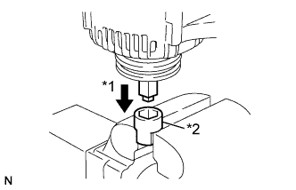
Text in Illustration *1 Insert *2 SST 2 Mount SST 2 in a vise.
-
Insert SST 1-A and 1-B into SST 2, and attach the generator pulley nut to SST 2.
-
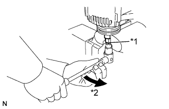
Text in Illustration *1 SST 1-A and 1-B *2 Turn To loosen the generator pulley nut, turn SST 1-A in the direction shown in the illustration.
Note
To prevent damage to the rotor shaft, do not loosen the generator pulley nut more than one-half turn.
-
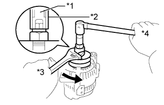
Text in Illustration *1 SST 1-A *2 SST 1-B *3 Turn *4 Hold Remove the generator from SST 2.
-
Turn SST 1-B, and remove SST 1-A and 1-B.
-
Remove the generator pulley nut and the generator pulley.
-
-
REMOVE GENERATOR BRUSH HOLDER ASSEMBLY
-
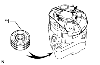
Text in Illustration *1 Pulley Place the generator on the generator pulley.
-
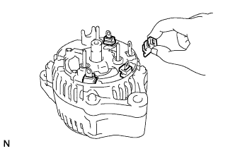
Remove the 3 nuts and No. 2 generator rear end cover.
-
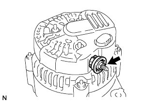
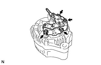
Remove the nut and terminal insulator.
-
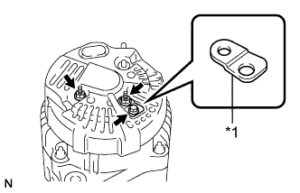
Text in Illustration *1 Terminal Plate Remove the bolt, 2 nuts, terminal plate and rear end cover.
-
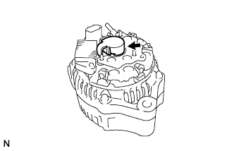
Remove the generator brush cover.
-
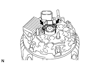
Remove the 2 screws and generator brush holder assembly.
-
-
REMOVE GENERATOR REGULATOR ASSEMBLY
-
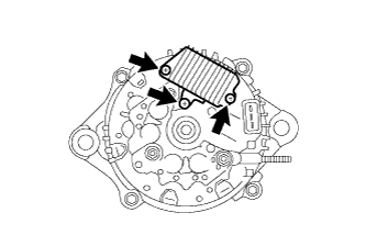
Remove the 3 screws and generator regulator assembly.
-
Remove the plate seal from the rectifier end frame.
-
-
REMOVE GENERATOR HOLDER WITH RECTIFIER
-
Remove the 4 screws and generator holder with rectifier.
-
-
REMOVE GENERATOR ROTOR ASSEMBLY
-
Remove the 4 rubber insulators.
-
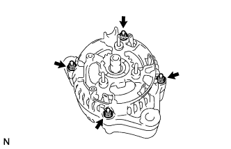
Remove the 4 nuts.
-
Text in Illustration *1 Turn *2 Hold Using a bearing puller, remove the rectifier end frame.
-
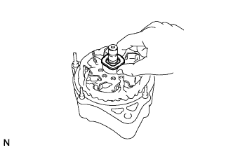
Remove the generator washer.
-
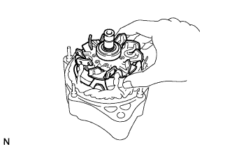
Remove the generator rotor assembly.
-
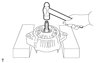
If the generator rotor assembly is difficult to remove, position the drive end frame horizontally as shown in the illustration and lightly tap the generator rotor assembly using a plastic hammer to remove the generator rotor assembly.
Note
Do not drop the generator rotor assembly.
-