STARTER INSPECTION

-
INSPECT STARTER ASSEMBLY
CAUTION:
As a large electric current passes through the cable during this inspection, a thick cable must be used. Otherwise, the cable may become hot and cause injury.
Note
The following tests must each be performed within 3 to 5 seconds to prevent the coil from burning out.
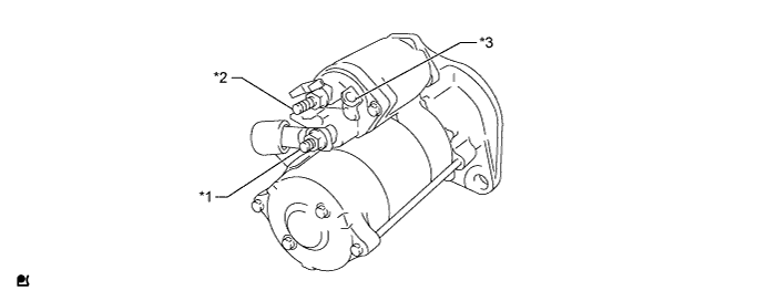
Text in Illustration *1 Terminal M *2 Terminal B *3 Terminal C - -
-
Mount the starter in a vise between aluminum plates.
-
Perform a pull-in test.
-
Remove the nut and 2 washers and disconnect the lead wire from terminal M.
-
Connect the battery to the magnet starter switch as shown in the illustration. Then check that the clutch pinion gear moves outward.
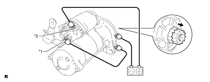
Text in Illustration *1 Terminal M *2 Terminal C 
Moves Outward - -
-
-
Perform a holding test.
-
Disconnect the negative (-) terminal lead from terminal M with the conditions specified in the pull-in test above being maintained. Check that the pinion gear remains out.
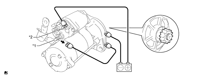
Text in Illustration *1 Terminal M *2 Terminal C Disconnect - -
-
-
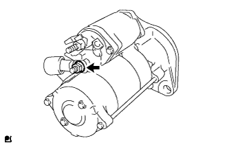
Inspect the clutch pinion gear return.
-
Disconnect the negative (-) lead from the starter body. Check that the clutch pinion gear returns inward.
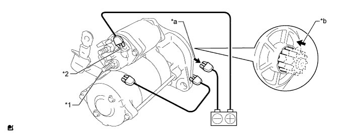
Text in Illustration *1 Terminal M *2 Terminal C *a Disconnect *b Returns Inward
-
-
Perform an operation test without load.
-
Connect the lead wire to terminal M with the 2 washers and nut.
- Torque:
- 14 N*m { 138 kgf*cm, 10 ft.*lbf }
-
Connect the battery and an ammeter to the starter with terminal C disconnected as shown in the illustration.
CAUTION:
Do not connect the battery to terminal C in this step.
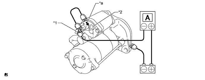
Text in Illustration *1 Terminal B *2 Terminal C *a Connect - - -
Connect the battery to terminal C and check that the starter rotates smoothly and steadily while the pinion gear is out.
Measure the current according to the value(s) in the table below.
Standard Current Tester Connection Condition Specified Condition Battery - Terminal C Always 180 A or less If the result is not as specified, repair or replace the starter assembly.
-
-
-
INSPECT STARTER ARMATURE ASSEMBLY
-
Check the surface of the commutator for dirt and burns.
If the surface is dirty or burnt, correct it with sandpaper (No. 400) or a lathe. If necessary, replace the starter armature assembly.
-
Inspect the commutator for an open circuit.
-
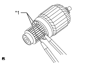
Text in Illustration *1 Segment Measure the resistance according to the value(s) in the table below.
Standard Resistance Tester Connection Condition Specified Condition Segment - Segment Always Below 1 Ω If the result is not as specified, replace the starter armature assembly.
-
-
Inspect the commutator for a short circuit.
-
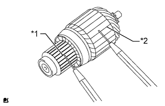
Text in Illustration *1 Segment *2 Armature Coil Core Measure the resistance according to the value(s) in the table below.
Standard Resistance Tester Connection Condition Specified Condition Segment - Armature coil core Always 10 kΩ or higher If the result is not as specified, replace the starter armature assembly.
-
-
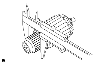
Using a vernier caliper, measure the commutator diameter.
Standard diameter 36.0 mm (1.42 in.) Minimum diameter 34.0 mm (1.34 in.) If the diameter is less than the minimum, replace the starter armature assembly.
-
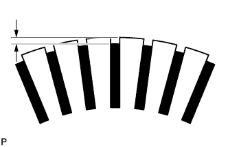
Check that the undercut portion is clean and free of foreign matter. Smooth out the edge.
Standard undercut depth 0.5 to 0.8 mm (0.0197 to 0.0315 in.) Minimum undercut depth 0.2 mm (0.00787 in.) If the undercut depth is less than the minimum, replace the starter armature assembly.
-
Check that the bearing rotates smoothly.
If necessary, replace the starter armature assembly.
-
Inspect the commutator circle runout.
-
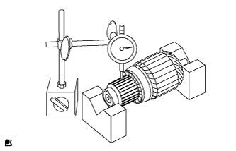
Place the starter armature assembly on V-blocks.
-
Using a dial gauge, measure the circle runout.
Maximum circle runout 0.1 mm (0.00394 in.) If the circle runout is more than the maximum, replace the starter armature assembly.
-
-
-
INSPECT STARTER YOKE ASSEMBLY
-
Inspect the starter yoke.
-
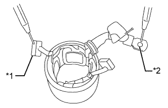
Text in Illustration *1 Brush *2 Lead Wire Measure the resistance according to the value(s) in the table below.
Standard Resistance Tester Connection Condition Specified Condition Brush - Lead wire Always Below 1 Ω If the result is not as specified, replace the starter yoke assembly.
-
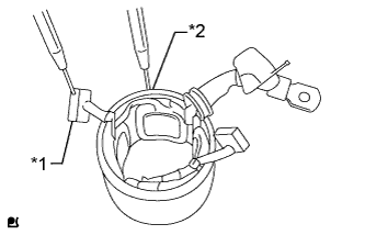
Text in Illustration *1 Brush *2 Starter Yoke Body Measure the resistance according to the value(s) in the table below.
Standard Resistance Tester Connection Condition Specified Condition Brush - Starter yoke body Always 10 kΩ or higher If the result is not as specified, replace the starter yoke assembly.
-
-
-
INSPECT STARTER BRUSH
-
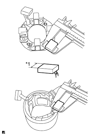
Text in Illustration *1 Length Using a vernier caliper, measure the starter brush length.
Standard length 18.0 mm (0.709 in.) Minimum length 13.0 mm (0.512 in.) If the length is less than the minimum, replace the starter brush holder assembly and starter yoke assembly.
Tech Tips
Replace all 4 starter brushes at the same time.
-
-
INSPECT STARTER BRUSH HOLDER ASSEMBLY
-
Check the resistance.
-
Measure the resistance according to the value(s) in the table below.
Standard Resistance Tester Connection Condition Specified Condition Positive (+) brush holder - Negative (-) brush holder Always 10 kΩ or higher If the result is not as specified, replace the starter brush holder assembly.
-
-
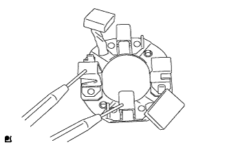
Inspect the load of the starter brush spring.
-
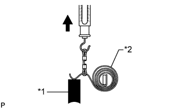
Text in Illustration *1 Brush *2 Brush Spring Using a pull scale, measure the installed load of the spring at the exact moment the starter brush spring separates from the starter brush.
Standard spring installed load 18 N (1.8 kgf, 4.0 lbf) Minimum spring installed load 13 N (1.3 kgf, 2.9 lbf) If the installed load is less than the minimum, replace the starter brush holder assembly.
-
-
-
INSPECT STARTER MOTOR HOUSING
-
Check the pull-in coil for an open circuit.
-
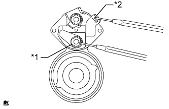
Text in Illustration *1 Terminal M *2 Terminal C Measure the resistance according to the value(s) in the table below.
Standard Resistance Tester Connection Condition Specified Condition Terminal C - Terminal M 20°C (68°F) 0.12 to 0.14 Ω If the result is not as specified, replace the starter assembly.
-
-
Check the holding coil for an open circuit.
-
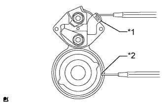
Text in Illustration *1 Terminal C *2 Starter Motor Housing Body Measure the resistance according to the value(s) in the table below.
Standard Resistance Tester Connection Condition Specified Condition Terminal C - Starter motor housing body 20°C (68°F) 1.13 to 1.25 Ω If the result is not as specified, replace the starter assembly.
-
-
Check the resistance.
-
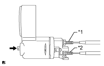
Text in Illustration *1 Terminal M *2 Terminal B Push Measure the resistance according to the value(s) in the table below.
Standard Resistance Tester Connection Switch Condition Specified Condition Terminal B - Terminal M Not pushed 10 kΩ or higher Pushed Below 1 Ω If the result is not as specified, replace the starter assembly.
-
-
-
INSPECT STARTER CLUTCH SUB-ASSEMBLY
-
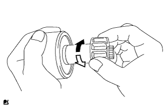
Check the starter clutch sub-assembly operation.
-
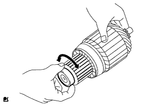
Grip the clutch in one hand and turn only the inner sleeve with the other hand.
Text in Illustration Free 
Lock -
Check that the inner sleeve turns easily in the "free" direction but cannot turn in the "lock" direction as shown in the illustration.
If the starter clutch sub-assembly does not operate as specified, replace the starter clutch sub-assembly.
-
-
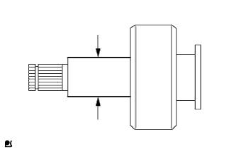
Using a micrometer, measure the outside diameter of the starter clutch sub-assembly.
Standard outside diameter 25.0 mm (0.984 in.) Minimum outside diameter 24.9 mm (0.980 in.) If the outside diameter is less than the minimum, replace the starter clutch sub-assembly.
-
-
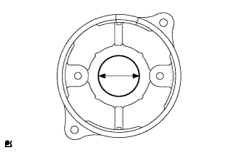
INSPECT STARTER DRIVE HOUSING BUSH
-
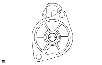
Using a cylinder gauge, measure the inside diameter of the starter drive housing bush.
Standard inside diameter 25.0 mm (0.984 in.) Maximum inside diameter 25.2 mm (0.992 in.) If the inside diameter is more than the maximum, replace the starter assembly.
-
-
INSPECT STARTER CENTER BEARING BUSH
-
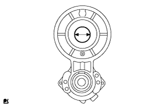
Using a cylinder gauge, measure the inside diameter of the starter center bearing bush.
Standard inside diameter 26.0 mm (1.02 in.) Maximum inside diameter 26.2 mm (1.03 in.) If the inside diameter is more than the maximum, replace the starter assembly.
-
-
INSPECT COMMUTATOR END FRAME
-
Using a cylinder gauge, measure the inside diameter of the commutator end frame.
Standard inside diameter 28.0 mm (1.10 in.) Maximum inside diameter 28.1 mm (1.11 in.) If the inside diameter is more than the maximum, replace the commutator end frame.
-