RADIATOR REASSEMBLY

-
INSPECT LOCK PLATE FOR DAMAGE
-
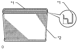
Text in Illustration *1 Lock Plate *2 Core Inspect the lock plate for damage.
If the sides of the lock plate groove are deformed, reassembly of the tank will be impossible. Correct any deformations with pliers.
Coolant will leak if the bottom of the lock plate groove is damaged or dented. Repair or replace it if necessary.
Note
The radiator can only be recaulked twice. After the second time, the radiator core must be replaced.
-
-
INSTALL RADIATOR UPPER TANK
-
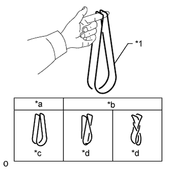
Text in Illustration *1 O-Ring *a CORRECT *b INCORRECT *c Normal *d Twisted Check that there are no foreign objects in the lock plate groove, and install a new O-ring. Make sure that the O-ring is not twisted.
Tech Tips
When cleaning the lock plate groove, lightly rub it with sandpaper without scratching it.
-
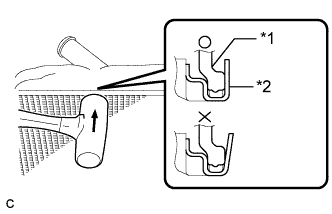
Text in Illustration *1 Radiator Upper Tank *2 Lock Plate Tap the lock plate with a plastic-faced hammer so that there is no gap between the lock plate and the radiator upper tank.
-
-
ASSEMBLE SST
-
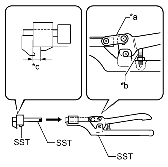
Text in Illustration *a Part A *b Stopper Bolt *c Dimension B Install the punch assembly to the overhaul handle, inserting it in the hole in part A as shown in the illustration.
- SST
- 09230-01010 ( 09231-01010, 09231-01020 )
- 09231-14010
-
While squeezing the handle, adjust the stopper bolt so that dimension B is as specified below.
Dimension B 7.4 to 7.8 mm (0.291 to 0.307 in.)
-
-
CAULK LOCK PLATE
-
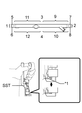
Text in Illustration *1 Lock Plate Lightly press SST against the lock plate in the order shown in the illustration. After repeating this a few times, fully crimp the lock plate by squeezing the handle until it is stopped by the stopper bolt.
- SST
- 09230-01010 ( 09231-01010, 09231-01020 )
- 09231-14010
Note
-
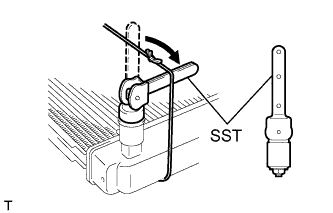
For positions where the crimping tool is not usable, crimp the lock plate using pliers.
-
Crimp the lock plate in the order shown in the illustration.
-
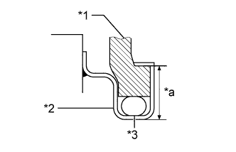
Text in Illustration *1 Tank *2 Lock Plate *3 O-Ring *a Height D Check height D after crimping the lock plate.
Standard height 7.4 to 7.8 mm (0.291 to 0.307 in.) -
In the event that height D is not within the standard range, adjust the stopper bolt of the handle once again and recrimp the lock plate.
Note
-
Check the height at both ends of the lock plate as well as around the central portion where crimping has not been performed (under the pipe, etc.).
-
After the radiator is recrimped once, make a mark in a clearly visible place to indicate that the radiator has been recrimped.
-
The radiator can only be recrimped twice. After the second time, the radiator core must be replaced.
-
-
-
INSTALL RADIATOR LOWER TANK
Tech Tips
Use the same procedure described for the radiator upper tank.
-
INSPECT FOR COOLANT LEAK
-
Plug the inlet and outlet pipes of the radiator with SST.
- SST
- 09230-01010 ( 09231-00030, 09231-00050 )
-
Using a radiator cap tester, apply pressure to the radiator.
Standard test pressure 118 kPa (1.2 kgf/cm2, 17 psi) -
Submerge the radiator in water.
-
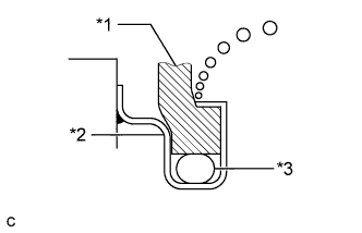
Text in Illustration *1 Tank *2 Lock Plate *3 O-Ring Inspect for leaks.
Tech Tips
For radiators with resin tanks, there is clearance between the tank and lock plate where a small amount of air will remain. This air is released when the radiator is submerged in water, giving the appearance of a leak. Before performing the water leak test, shake the radiator in the water until all air bubbles are released.
-
-
INSTALL RADIATOR SIDE PLATE
-
Install the 2 radiator collars and 2 radiator bushings.
-
Install the 2 radiator side plates with the 4 bolts.
- Torque:
- 13 N*m { 130 kgf*cm, 9 ft.*lbf }
-
-
INSTALL RADIATOR DRAIN COCK PLUG
-
Install a new O-ring and the radiator drain cock plug.
-