WATER PUMP INSTALLATION

-
INSTALL WATER PUMP ASSEMBLY
-
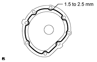
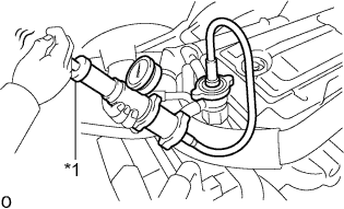
Apply a continuous bead of seal packing (diameter 1.5 to 2.5 mm (0.06 to 0.10 in.)) as shown in the illustration.
Seal packing Toyota Genuine Seal Packing Black, Three Bond 1207B or equivalent Note
-
Remove any oil from the contact surfaces.
-
Install the water pump within 3 minutes of applying the seal packing.
-
Do not start the engine for at least 2 hours after the installation.
-
-

Install the water pump assembly with the 8 bolts.
- Torque:
- 29 N*m { 290 kgf*cm, 21 ft.*lbf }
-
-
INSTALL FAN PULLEY
-
Install the fan pulley.
-
-
INSTALL FAN
-
Temporarily install the fan with the 4 nuts.
-
Install the fan and generator V belt Click here.
-
Holding the V belt, tighten the 4 nuts completely to install the fan pulley and fan properly.
- Torque:
- 29 N*m { 291 kgf*cm, 21 ft.*lbf }
-
-
INSPECT DRIVE BELT
-
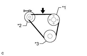
Text in Illustration *1 Fan Pulley *2 Generator *3 Crankshaft Pulley Check the fan and generator V belt deflection.
Tech Tips
-
The specified deflection values per belt are shown in the following table.
-
When inspecting the V belt deflection, apply 98 N (10 kgf, 22 lbf) tensile force to it.
Deflection Item Specified Condition New belt 10.5 to 12.5 mm (0.413 to 0.492 in.) Used belt 12.5 to 16.0 mm (0.492 to 0.630 in.) Note
-
Check the V belt deflection at the specified point.
-
When inspecting a belt which has been used for over 5 minutes, apply the used belt specifications.
-
-
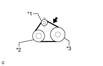
Text in Illustration *1 Idler Pulley *2 A/C Compressor *3 Crankshaft Pulley Check the No. 1 V (cooler compressor to crankshaft pulley) belt deflection (w/ Air Conditioning System).
Tech Tips
-
The specified deflection values per belt are shown in the following table.
-
When inspecting the V belt deflection, apply 98 N (10 kgf, 22 lbf) tensile force to it.
Deflection Item Specified Condition New belt 8.5 to 10.0 mm (0.335 to 0.394 in.) Used belt 10.0 to 12.0 mm (0.394 to 0.472 in.) Note
-
Check the V belt deflection at the specified point.
-
When inspecting a belt which has been used for over 5 minutes, apply the used belt specifications.
-
-
-
INSTALL INLET RADIATOR HOSE
-
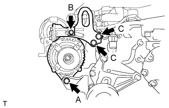
Temporarily install the generator assembly with the bolt (A).
-
Temporarily install the generator belt adjusting bar to the generator assembly with the bolt (B).
-
Install the generator belt adjusting bar with the 2 bolts (C).
- Torque:
- 125 N*m { 1275 kgf*cm, 92 ft.*lbf }
-
Connect the 3 wire harness clamps.
-
Connect the connector to the generator.
-
Install the wire harness to terminal B with the nut, and install the terminal cap.
- Torque:
- 10 N*m { 102 kgf*cm, 7 ft.*lbf }
-
-
ADD ENGINE COOLANT
-
Add engine coolant.
Specified capacity 14.7 liters (15.5 US qts, 12.9 Imp. qts) Note
Never use water as a substitute for engine coolant.
Tech Tips
-
TOYOTA vehicles are filled with TOYOTA SLLC at the factory. In order to avoid damage to the engine cooling system and other technical problems, only use TOYOTA SLLC or similar high quality ethylene glycol based non-silicate, non-amine, non-nitrite, non-borate coolant with long-life hybrid organic acid technology (coolant with long-life hybrid organic acid technology is a combination of low phosphates and organic acids).
-
Contact your TOYOTA dealer for further details.
-
-
Check the coolant level inside the radiator by squeezing the inlet and outlet radiator hoses several times by hand. If the coolant level goes down, add coolant.
-
Install the radiator cap sub-assembly.
-
Slowly pour coolant into the radiator reservoir until it reaches the full line.
-
Bleed air from the cooling system.
-
Warm up the engine until the thermostat opens.
While the thermostat is open, circulate the coolant for several minutes.
-
Press the inlet and outlet radiator hoses several times by hand to bleed air.
Note
-
Be careful as the radiator hoses are hot.
-
Keep your hands away from the radiator fan.
-
-
-
Stop the engine and wait until the coolant cools down.
-
Remove the radiator cap sub-assembly and check the coolant level.
-
If the coolant level has dropped, add coolant.
-
Check the coolant level inside the radiator reservoir tank again. If it is below the full level, add coolant.
-
-
INSPECT FOR COOLANT LEAK
-
Remove the radiator cap sub-assembly.
CAUTION:
Do not remove the radiator cap sub-assembly while the engine and radiator are still hot. Pressurized, hot engine coolant and steam may be released and cause serious burns.
-
Text in Illustration *1 Radiator Cap Tester Fill the radiator with coolant and attach a radiator cap tester.
-
Warm up the engine.
-
Using a radiator cap tester, increase the pressure inside the radiator to 137 kPa (1.4 kgf/cm2, 19.9 psi), and check that the pressure does not drop.
If the pressure drops, check the hoses, radiator and water pump for leaks. If no external leaks are found, check the heater core, cylinder block and cylinder head.
-
Install the radiator cap sub-assembly.
-