TURBOCHARGER REMOVAL

-
TILT UP CAB
CAUTION:
-
Make sure that the vehicle is on a level surface before tilting the cab up.
-
Make sure that all the doors are closed before tilting the cab up.
-
Make sure that nobody is inside or near the cab when tilting it up.
-
Be sure to have 2 people tilt the cab up when a heavy object such as a roof rack or cargo carrier is installed to the cab.
-
Be sure to remove anything set on top of the cab before tilting it up.
-
Make sure that the cab is securely locked in place after it is tilted up.
-
Make sure that there are no tools, cloths, etc. left in the engine room before tilting the cab back down.
-
Make sure that the cab is securely locked in place after tilting it back down.
-
-
REMOVE EXHAUST RETARDER ASSEMBLY
-
REMOVE EGR COOLER SUB-ASSEMBLY
-
REMOVE GENERATOR ASSEMBLY
-
for 60A Type: Click here
-
for 80A Type: Click here
-
-
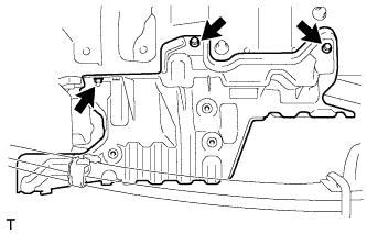
REMOVE ENGINE SIDE COVER SUB-ASSEMBLY RH
-
Remove the 4 bolts and engine side cover sub-assembly RH.
-
-
REMOVE ENGINE UNDER COVER RH
-
Remove the 2 bolts, nut and engine under cover RH.
-
-
REMOVE AIR HOSE ASSEMBLY
-
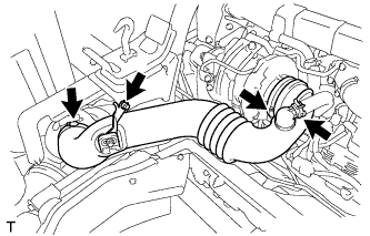
Slide the clamp and disconnect the ventilation hose from the air hose assembly.
-
Loosen the 2 hose clamps.
-
Remove the bolt and air hose assembly.
-
-
REMOVE NO. 2 AIR HOSE
-
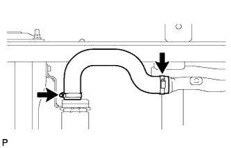
Loosen the 2 hose clamps and remove the No. 2 air hose from the intake pipe and intercooler assembly.
-
-
REMOVE INTAKE PIPE
-
Text in Illustration *1 No. 2 Intake Air Connector Bracket Remove the 2 bolts and No. 2 intake air connector bracket.
-
Remove the 2 nuts, intake pipe and gasket.
-
-
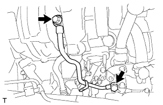
REMOVE NO. 1 TURBO WATER PIPE SUB-ASSEMBLY
-
Remove the union bolt, 2 gaskets, bolt and No. 1 turbo water pipe sub-assembly.
-
Remove the O-ring from the No. 1 turbo water pipe sub-assembly.
-
-
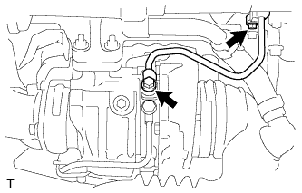
REMOVE TURBO OIL INLET PIPE SUB-ASSEMBLY
-
Disconnect the engine oil pressure switch connector.
-
Remove the 2 union bolts, 4 gaskets, bolt and turbo oil inlet pipe sub-assembly.
-
-
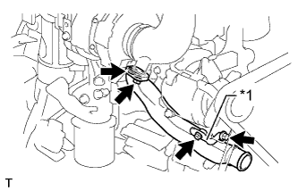
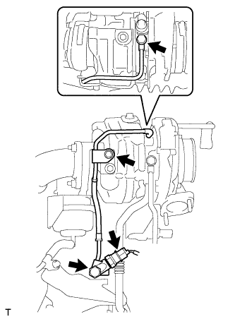
REMOVE NO. 2 TURBO WATER PIPE SUB-ASSEMBLY
-
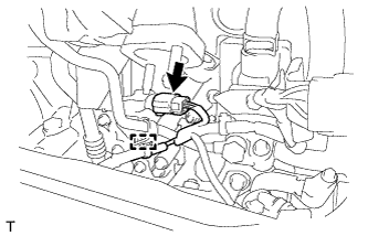
Disconnect the connector from the turbocharger sub-assembly.
-
Detach the wire harness clamp.
-
Remove the 2 union bolts, 4 gaskets and No. 2 turbo water pipe sub-assembly.
-
-
REMOVE TURBO OIL OUTLET PIPE
-
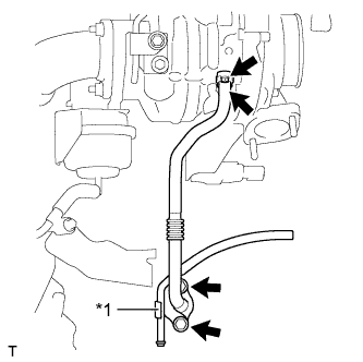
Text in Illustration *1 No. 2 Water By-pass Pipe Sub-assembly Remove the 2 bolts and disconnect the No. 2 water by-pass pipe sub-assembly from the turbo oil outlet pipe.
-
Remove the 2 bolts, 2 gaskets and turbo oil outlet pipe.
-
-
REMOVE NO. 1 TURBO INSULATOR
-
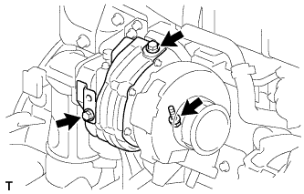
Remove the 3 bolts and No. 1 turbo insulator.
-
-
REMOVE TURBOCHARGER SUB-ASSEMBLY
-
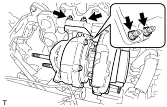
Remove the 4 nuts, 4 spacers, turbocharger sub-assembly and gasket.
-
Replace the 6 stud bolts.
Tech Tips
If a stud bolt is deformed or the threads are damaged, replace it.
-