TURBOCHARGER INSTALLATION

-
INSTALL TURBOCHARGER SUB-ASSEMBLY
-
Install a new gasket and turbocharger sub-assembly with 4 new nuts and 4 spacers.
- Torque:
- 70 N*m { 714 kgf*cm, 52 ft.*lbf }
-
-
INSTALL NO. 1 TURBO INSULATOR
-
Install the No. 1 turbo insulator with the 3 bolts.
- Torque:
- 29 N*m { 291 kgf*cm, 21 ft.*lbf }
-
-
INSTALL TURBO OIL OUTLET PIPE
-
Install 2 new gaskets, the No. 2 water by-pass pipe sub-assembly and the turbo oil outlet pipe with the 4 bolts.
- Torque:
- 29 N*m { 291 kgf*cm, 21 ft.*lbf }
-
-
INSTALL NO. 2 TURBO WATER PIPE SUB-ASSEMBLY
-
Install 4 new gaskets and No. 2 turbo water pipe sub-assembly with the 2 union bolts.
- Torque:
- 25 N*m { 250 kgf*cm, 18 ft.*lbf }
-
Connect the connector to the turbocharger sub-assembly.
-
Attach the wire harness clamp.
-
-
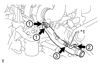
INSTALL TURBO OIL INLET PIPE SUB-ASSEMBLY
-
Install 4 new gaskets and turbo oil inlet pipe sub-assembly, and temporarily install the 2 union bolts and bolt.
-
Tighten the 2 union bolts.
- Torque:
- 25 N*m { 250 kgf*cm, 18 ft.*lbf }
-
Tighten the bolt.
- Torque:
- 29 N*m { 291 kgf*cm, 21 ft.*lbf }
-
Connect the engine oil pressure switch connector.
-
-
INSTALL NO. 1 TURBO WATER PIPE SUB-ASSEMBLY
-
Install a new O-ring to the No. 1 turbo water pipe sub-assembly.
-
Install 2 new gaskets and the No. 1 turbo water pipe sub-assembly, and temporarily install the union bolt and bolt.
-
Tighten the union bolt.
- Torque:
- 25 N*m { 250 kgf*cm, 18 ft.*lbf }
-
Tighten the bolt.
- Torque:
- 29 N*m { 291 kgf*cm, 21 ft.*lbf }
-
-
INSTALL INTAKE PIPE
-
Text in Illustration *1 No. 2 Intake Air Connector Bracket Install a new gasket and the intake pipe, and temporarily install the 2 nuts.
-
Install the No. 2 intake air connector bracket and temporarily install the 2 bolts.
-
Tighten the 2 nuts and 2 bolts in order from 1 to 3.
- Torque:
- 29 N*m { 291 kgf*cm, 21 ft.*lbf }
-
-
INSTALL NO. 2 AIR HOSE
Note
Thoroughly degrease the No. 2 air hose and the points where it connects to the vehicle before installation.
-
Install 2 new hose clamps to the No. 2 air hose.
-
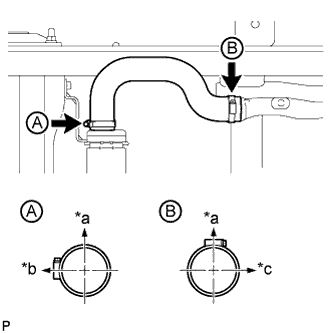
Text in Illustration *a Upper Side *b Front Side of Vehicle *c RH Side Install the No. 2 air hose to the intake pipe and intercooler assembly and tighten the 2 hose clamps.
- Torque:
- 6.3 N*m { 64 kgf*cm, 56 in.*lbf }
Tech Tips
The direction of each hose clamp is indicated in the illustration.
-
Retighten the 2 hose clamps after waiting 10 minutes or more.
- Torque:
- 6.3 N*m { 64 kgf*cm, 56 in.*lbf }
-
-
INSTALL AIR HOSE ASSEMBLY
-
Install 2 new hose clamps to the air hose assembly.
-
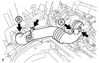
Install the air hose assembly with the bolt.
- Torque:
- 20 N*m { 199 kgf*cm, 14 ft.*lbf }
-
Tighten the 2 hose clamps.
- Torque:
- for hose clamp A
- 6.3 N*m { 64 kgf*cm, 56 in.*lbf }
- for hose clamp B
- 3.7 N*m { 38 kgf*cm, 33 in.*lbf }
-
Install the ventilation hose to the air hose assembly, and slide the clamp to secure the hose.
-
-
INSTALL ENGINE UNDER COVER RH
-
Install the engine under cover RH with the 2 bolts and nut.
- Torque:
- for bolt
- 31 N*m { 316 kgf*cm, 23 ft.*lbf }
- for nut
- 20 N*m { 199 kgf*cm, 14 ft.*lbf }
-
-
INSTALL ENGINE SIDE COVER SUB-ASSEMBLY RH
-
Install the engine side cover sub-assembly RH with the 4 bolts.
- Torque:
- 12 N*m { 117 kgf*cm, 8 ft.*lbf }
-
-
INSTALL GENERATOR ASSEMBLY
-
for 60A Type: Click here
-
for 80A Type: Click here
-
-
INSTALL EGR COOLER SUB-ASSEMBLY
-
INSTALL EXHAUST RETARDER ASSEMBLY