INTAKE SYSTEM ON-VEHICLE INSPECTION

-
TILT UP CAB
CAUTION:
-
Make sure that the vehicle is on a level surface before tilting the cab up.
-
Make sure that all the doors are closed before tilting the cab up.
-
Make sure that nobody is inside or near the cab when tilting it up.
-
Be sure to have 2 people tilt the cab up when a heavy object such as a roof rack or cargo carrier is installed to the cab.
-
Be sure to remove anything set on top of the cab before tilting it up.
-
Make sure that the cab is securely locked in place after it is tilted up.
-
Make sure that there are no tools, cloths, etc. left in the engine room before tilting the cab back down.
-
Make sure that the cab is securely locked in place after tilting it back down.
-
-
INSPECT INTAKE SYSTEM
-
Check that there is no air suction or leaks at the points shown in the illustration.
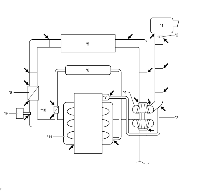
Text in Illustration *1 Air Cleaner Assembly *2 Intake Mass Air Flow Meter Sub-assembly *3 Ventilation Hose *4 Turbocharger Sub-assembly *5 Intercooler Assembly *6 EGR Cooler Sub-assembly *7 Oil Separator Assembly *8 Venturi Assembly *9 Manifold Absolute Pressure Sensor *10 EGR Valve Assembly *11 Intake Manifold - -
-
-
CHECK TURBOCHARGING PRESSURE
-
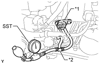
Text in Illustration *1 Manifold Absolute Pressure Sensor *2 3-way Connector Using a 3-way connector, connect SST (turbocharger pressure gauge) to the hose leading to the intake manifold.
- SST
- 09992-00242
-
Fully apply the parking brake and chock the 4 wheels.
-
While depressing the clutch pedal, fully depress the accelerator pedal. Measure the boost pressure at maximum engine speed (approximately 3300 to 3400 rpm).
Standard pressure (Gauge pressure) 17 kPa (0.2 kgf/cm2, 2.5 psi) or higher
-
-
INSPECT TURBOCHARGER CONTROL ACTUATOR
-
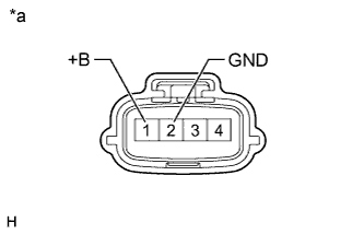
Text in Illustration *a Front view of wire harness connector
(to Turbocharger Sub-assembly)
Check the voltage of the turbocharger control actuator.
-
Disconnect the turbocharger connector from the turbocharger sub-assembly.
-
Turn the ignition switch to ON.
-
Measure the voltage according to the value(s) in the table below.
Standard Voltage Tester Connection Switch Condition Specified Condition 1(+B) - 2(GND) Ignition switch ON 16 to 32 V If the voltage is not as specified, check the wire harness and connector.
-
-
-
CHECK WARNING LIGHT
-
Check that the MIL turns on when the ignition switch is turned to ON and that the MIL turns off when the engine is started.
-
Text in Illustration *1 Manifold Absolute Pressure Sensor *2 3-way Connector Using a 3-way connector, connect SST (turbocharger pressure gauge) to the hose leading to the intake manifold.
- SST
- 09992-00242
-
During idling, check that the MIL turns on when pressure is applied using the SST (turbocharger pressure gauge).
OK The MIL illuminates at 150 kPa (1.5 kgf/cm2, 22 psi) or higher -
Clear the DTCs Click here.
-
-
INSPECT TURBOCHARGER SUB-ASSEMBLY
CAUTION:
-
Wear protective gloves to prevent injuries and burns when checking the turbocharger sub-assembly.
-
The engine compartment becomes hot when the engine is running.
-
Remove the No. 1 turbo insulator Click here.
-
Make sure that the connector is properly connected.
-
Check that the variable nozzle link operates when the ignition switch is turned from ON to off.
Note
Never loosen or tighten the lock nut of the stopper.
Tech Tips
When the ignition switch is turned off, the variable nozzle link operates as shown in the illustration.
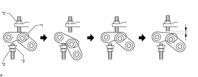
Text in Illustration *1 Variable Nozzle Link *2 Lock Nut -
Install the No. 1 turbo insulator Click here.
-