INTAKE SYSTEM ON-VEHICLE INSPECTION

-
CHECK TURBOCHARGER PRESSURE
-
Warm up the engine.
-
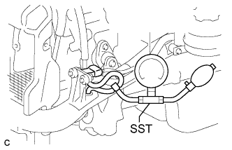
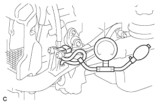
Using a 3-way connector, connect SST (turbocharger pressure gauge) to the hose between the turbo pressure sensor and the No. 1 air hose.
- SST
- 09992-00242
-
Depress the clutch pedal, and then fully depress the accelerator pedal. Measure the turbocharging pressure at maximum speed (approximately 3500 to 3600 rpm).
Standard pressure 40 to 70 kPa (0.40 to 0.71 kgf/cm2, 5.8 to 10.2 psi) If the pressure is less than the minimum, check the intake air and exhaust system for leakage. If there is no leakage, perform the "check motor for turbocharger control operation" procedures below. If the result is not as specified, replace the turbocharger.
-
-
INSPECT TURBO PRESSURE SENSOR
-
Inspect the power source voltage.
-
Disconnect the sensor connector.
-
Turn the ignition switch to the ON position.
-
Measure the voltage between terminals T7-3 (VC) and T7-1 (E) of the wire harness side connector.
Standard voltage 4.5 to 5.5 V If the result is not as specified, inspect the wire harness or ECM Click here.
-
Turn the ignition switch off.
-
Connect the sensor connector.
-
-
Check the power supply.
-
Turn the ignition switch to the ON position.
-
Disconnect the vacuum hose from the sensor.
-
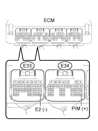
Connect a voltmeter to terminals E34-28 (PIM (+)) and E33-28 (E2 (-)) of the ECM.
-
Using SST (a turbocharger pressure gauge), apply the following amount of pressure.
- SST
- 09992-00242
Measure the voltage.
Standard voltage Applied Pressure kPa (kgf/cm2, psi)
Specified condition 93.0 (0.95, 13.5) 0.25 to 0.40 V 150 (1.53, 21.8) 1.0 to 1.4 V If the result is not as specified, replace the turbo pressure sensor.
-
Turn the ignition switch off.
-
Connect the vacuum hose.
-
-
-
CHECK MOTOR FOR TURBOCHARGER CONTROL OPERATION
-
Remove the No. 1 turbo insulator Click here.
-
Check the stroke.
Note
Make sure that the DC motor connectors are properly installed.
-
Turn the ignition switch ON and off.
-
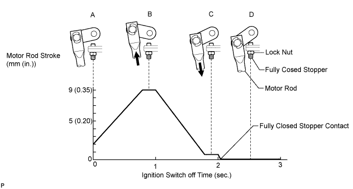
Check the turbocharger control actuator (DC motor) operation. Check that the actuator rod stroke is as shown in the illustration below.
Note
Never loosen or tighten the fully closed stopper lock nut.
If the result is not as specified, check the ECM Click here and turbocharger control actuator.
-
-
-
INSPECT TURBOCHARGER CONTROL ACTUATOR
-
Check the voltage of the turbocharger control actuator.
-
Turn the ignition switch to the ON position.
-
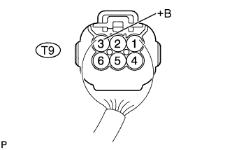
Measure the voltage of the actuator.
Standard voltage Tester Connection Specified Condition T9-3 (+B) - Body ground 16 to 32 V If the voltage is not as specified, check the wire harness and connector.
-
-
Check the resistance of the wire harness side connector.
-
Turn the ignition switch off.
-
Disconnect the T9 turbocharger control actuator connector.
-
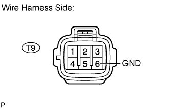
Measure the resistance.
Standard resistance Tester Connection Specified Condition T9-6 (GND) - Body ground Below 1 Ω If the resistance is not as specified, check the wire harness and connector.
-
-
Connect the T9 turbocharger control actuator connector.
-
Check the turbo motor signal.
-
Connect an oscilloscope to the terminals of the ECM.
-
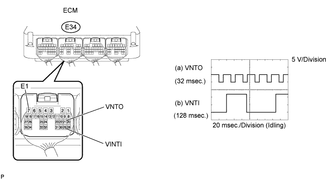
While idling the engine, check the waveform of the ECM.
Standard condition ECM Terminal (a) Between E34-21 (VNTO) and E34-7 (E1)
(b) Between E34-29 (VNTI) and E34-7 (E1)
Tester Range 5 V/Division, 20 msec./Division Specified Condition Idling with warm engine If the result is not as specified, replace the turbocharger assembly.
Tech Tips
The waveform varies depending on the turbocharger operation.
-
-