EMISSION CONTROL SYSTEM ON-VEHICLE INSPECTION

Tech Tips
When a malfunction in which the EGR system is always on occurs, black or white smoke may be emitted from the exhaust pipe.
-
TILT UP CAB
CAUTION:
-
Make sure that the vehicle is on a level surface before tilting the cab up.
-
Make sure that all the doors are closed before tilting the cab up.
-
Make sure that nobody is inside or near the cab when tilting it up.
-
Be sure to have 2 people tilt the cab up when a heavy object such as a roof rack or cargo carrier is installed to the cab.
-
Be sure to remove anything set on top of the cab before tilting it up.
-
Make sure that the cab is securely locked in place after it is tilted up.
-
Make sure that there are no tools, cloths, etc. left in the engine room before tilting the cab back down.
-
Make sure that the cab is securely locked in place after tilting it back down.
-
-
CHECK SEATING OF EGR VALVE
-
Start the engine. Check that the engine starts and then idles.
-
-
CHECK EGR VALVE OPERATION
-
Replace the normal DLC3 cable (12 V specification) for the intelligent tester with the 24 V DLC3 cable.
Note
Be sure to use the 24 V DLC3 cable when connecting the intelligent tester to the DLC3. Using the normal DLC3 cable (12 V specification) will cause damage to the tester.
-
Connect the intelligent tester to the DLC3.
-
Turn the ignition switch to ON.
-
Enter the following menus: Powertrain / Engine and ECT / Active Test / Control the EGR Step Position.
-
Check the Data List / Target EGR Position and Actual EGR valve pos.
OK Control Range Condition Specified Condition Active Test performed (Set EGR position to 0% → 30% → 60% → 90% → 60% → 30% → 0%) Actual EGR valve opening percentage changes according to Active Test operation If the result is not as specified, refer to DTC P1458 Click here.
-
-
VISUALLY CHECK HOSES, CONNECTIONS AND GASKETS
-
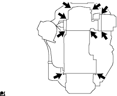
Visually check that the hoses, connections and gaskets have no cracks, leaks or damage.
Note
-
Detachment or other problems with the engine oil dipstick, filler cap, PCV hose and other components may cause the engine to run improperly.
-
Air suction caused by disconnections, looseness or cracks in the parts of the air induction system between the throttle body and cylinder head will cause engine failure or engine malfunction.
If the result is not as specified, replace the parts as necessary.
-
-
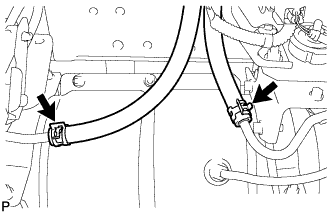
Check if the differential pressure sensor hoses are connected incorrectly, disconnected, leaking, cracked or otherwise damaged.
-
-
AIR BLOW OPERATION
Tech Tips
Clean the filter with compressed air if the DPF differential pressure is higher than the standard value. It is probable that excessive particulate matter has accumulated in the DPF.
-
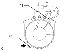
Text in Illustration *1 Exhaust Gas Temperature Sensor *2 Center Pipe Plug Remove the center pipe plug shown in the illustration.
Note
The center pipe may be hot. Make sure that the pipe is not hot before removing the center pipe plug.
Tech Tips
Do not remove the center pipe.
-
Remove the exhaust gas temperature sensor shown in the illustration Click here.
Tech Tips
Temporarily cover the hole with tape after removing the exhaust gas temperature sensor.
-
Apply compressed air.
-
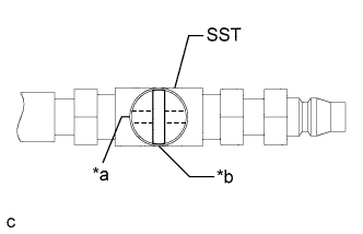
Text in Illustration *a Open *b Closed Close the air valve as illustrated and connect an air hose to SST securely.
- SST
- 09950-E9010
-
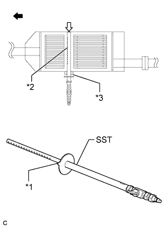
Text in Illustration *1 Tab *2 Air Holes *3 Plug Hole 
Front Side 
Inner Wall Face the SST air holes towards the front of the vehicle and fully insert SST through the plug hole until it contacts the inner wall of the center pipe.
- SST
- 09950-E9010
Tech Tips
The tab on the disc of SST is provided to allow the operator to determine the direction of the air holes when SST is inside the plug hole.
-
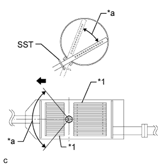
Text in Illustration *1 Catalytic Converter *a Air Blow Range Front Side Open the air valve and move SST within the range as shown in the illustration for 5 minutes while lightly pushing on the inner wall of the center pipe with SST.
- SST
- 09950-E9010
Note
-
Be careful not to hit the catalytic converters with SST.
-
Do not apply compressed air to the rear catalytic converter.
-
-
Close the air valve and remove SST.
-
Install the exhaust gas temperature sensor Click here.
Tech Tips
Remove the tape and any particulate matter on or around the exhaust gas temperature sensor installation hole.
-
Install the center pipe plug.
- Torque:
- 40 N*m { 408 kgf*cm, 30 ft.*lbf }
Note
Before installing the center pipe plug, clean the threads and apply anti-seize lubricant.
-