FUEL FILTER (for Fuel Tank Side) REPLACEMENT

Note
Do not allow any brake fluid or products which contain organic solvents (part cleaner, paint, etc.) to adhere to the fuel prefilter case.
-
REMOVE FUEL FILTER ASSEMBLY
-
w/ Fuel Heater:
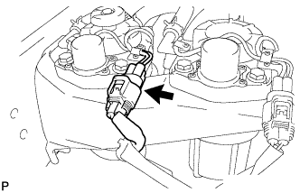
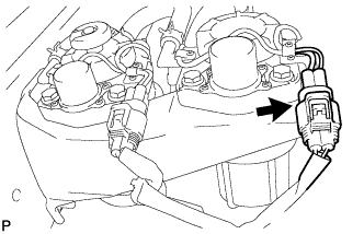
Disconnect the fuel heater connector.
-
Disconnect the level warning switch connector.
-
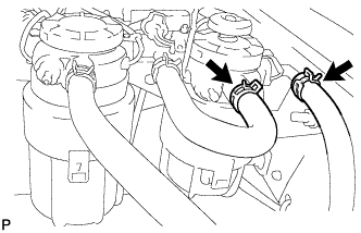
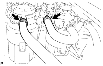
Slide the clip and disconnect the 2 fuel hoses from the fuel filter assembly.
-
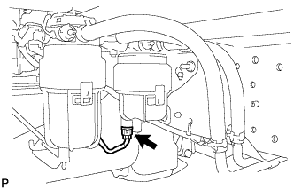
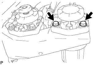
Remove the 2 bolts and fuel filter assembly.
-
-
REMOVE FUEL FILTER ELEMENT SUB-ASSEMBLY
-
Place a drain pan under the filter.
-
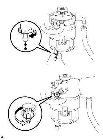
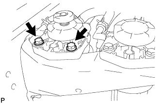
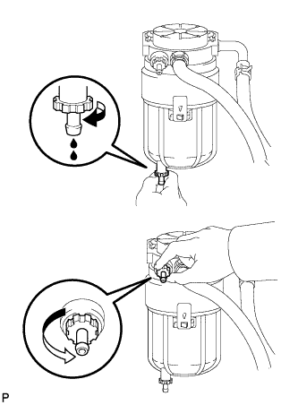
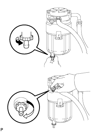
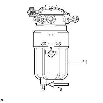
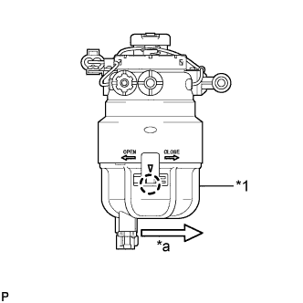
Loosen the drain plug and air bleeder plug as shown in the illustration. Drain the fuel.
Note
-
Do not use any tools.
-
Do not spill any fuel.
-
If any fuel is spilt on any part, wipe it clean with a piece of cloth.
-
-
When fuel stops draining from the drain plug, tighten the drain plug and air bleeder plug.
Note
Do not use any tools.
-
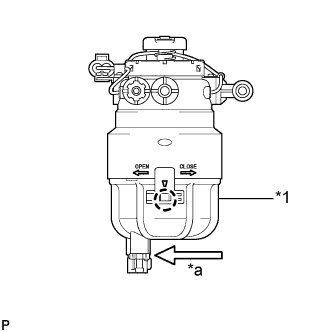
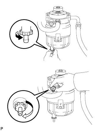
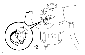
Text in Illustration *1 Fuel Filter Case *a Turn Detach the claw. Then, remove the fuel filter case by turning it approximately 120° counterclockwise.
-
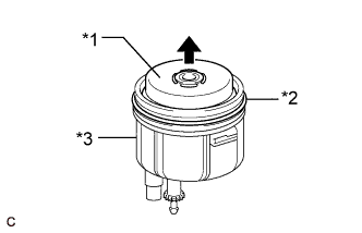
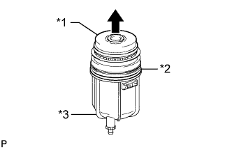
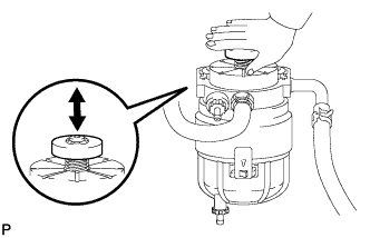
Text in Illustration *1 Fuel Filter Element Sub-assembly *2 O-ring *3 Fuel Filter Case Remove the fuel filter element sub-assembly.
-
Remove the O-ring from the fuel filter case.
-
-
REMOVE FUEL PREFILTER ASSEMBLY
-
w/ Fuel Heater:
Disconnect the fuel heater connector.
-
Slide the clip and disconnect the 2 fuel hoses from the fuel prefilter assembly.
-
Remove the 2 bolts and fuel prefilter assembly.
-
-
REMOVE FUEL PREFILTER ELEMENT SUB-ASSEMBLY
-
Place a drain pan under the prefilter.
-
Loosen the drain plug and air bleeder plug as shown in the illustration. Drain the fuel.
Note
-
Do not use any tools.
-
Do not spill any fuel.
-
If any fuel is spilt on any part, wipe it clean with a piece of cloth.
-
-
When fuel stops draining from the drain plug, tighten the drain plug and air bleeder plug.
Note
Do not use any tools.
-
Text in Illustration *1 Fuel Prefilter Case *a Turn Detach the claw. Then, remove the fuel prefilter case by turning it approximately 120° counterclockwise.
-
Text in Illustration *1 Fuel Prefilter Element Sub-assembly *2 O-ring *3 Fuel Prefilter Case Remove the fuel prefilter element sub-assembly.
-
Remove the O-ring from the fuel prefilter case.
-
Remove the float from the fuel prefilter case.
-
-
INSTALL FUEL PREFILTER ELEMENT SUB-ASSEMBLY
-
Install the float to the fuel prefilter case.
-
Install a new fuel prefilter element sub-assembly to the fuel prefilter case.
-
Apply a light coat of gasoline or grease to a new O-ring and install the O-ring to the fuel prefilter case.
-
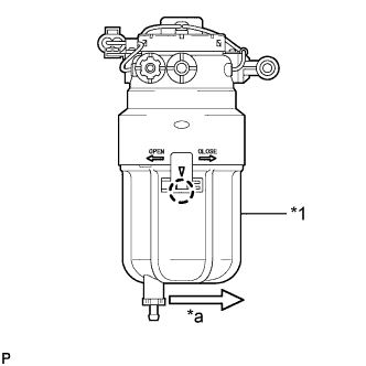
Text in Illustration *1 Fuel Prefilter Case *a Turn Install the fuel prefilter case by turning it clockwise until the claw is attached.
-
-
INSTALL FUEL PREFILTER ASSEMBLY
-
Install the fuel prefilter assembly with the 2 bolts.
- Torque:
- 18 N*m { 178 kgf*cm, 13 ft.*lbf }
-
Connect the 2 fuel hoses to the fuel prefilter assembly and slide the clip to secure the hose.
-
w/ Fuel Heater:
Connect the fuel heater connector.
-
-
INSTALL FUEL FILTER ELEMENT SUB-ASSEMBLY
-
Install a new fuel filter element sub-assembly to the fuel filter case.
-
Apply a light coat of gasoline or grease to a new O-ring and install the O-ring to the fuel filter case.
-
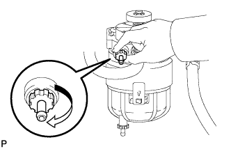
Text in Illustration *1 Fuel Filter Case *a Turn Install the fuel filter case by turning it clockwise until the claw is attached.
-
-
INSTALL FUEL FILTER ASSEMBLY
-
Install the fuel filter assembly with the 2 bolts.
- Torque:
- 18 N*m { 178 kgf*cm, 13 ft.*lbf }
-
Connect the 2 fuel hoses to the fuel filter assembly, and slide the 2 clips to secure them.
-
Connect the level warning switch connector.
-
w/ Fuel Heater:
Connect the fuel heater connector.
-
-
BLEED AIR FROM FUEL SYSTEM
-
Confirm that the drain plug and air bleeder plug of the fuel filter assembly and fuel prefilter assembly are completely closed.
-
Text in Illustration *1 Air Bleeder Plug *2 Fuel Filter Assembly Loosen the air bleeder plug of the fuel filter assembly.
Note
Do not loosen the air bleeder plug of the fuel prefilter assembly.
-
Pump the priming pump until air stops coming out of the pipe of the air bleeder plug.
Note
-
Place a container, etc. underneath the fuel filter to prevent fuel from spraying.
-
The hand pump must be pushed with a full stroke during pumping.
-
The maximum hand pump pumping speed is 2 strokes per second.
-
When the fuel pressure at the supply pump inlet port reaches a saturated pressure, the hand pump resistance increases.
-
If pumping is interrupted during the air bleeding process, fuel in the fuel line may return to the fuel tank. Continue pumping until the hand pump resistance increases.
-
If the hand pump resistance does not increase despite consecutively pumping 200 times or more, there may be a fuel leak between the fuel tank and fuel filter, the hand pump may be malfunctioning, or the vehicle may have run out of fuel.
-
If air bleeding using the hand pump is incomplete, the common rail pressure does not rise to the pressure range necessary for normal use and the engine cannot be started.
-
-
Tighten the air bleeder plug.
Note
Do not use any tools.
-
Check if the engine starts.
Note
-
Even if air bleeding using the hand pump has been completed, the starter may need to be cranked for 10 seconds or more to start the engine.
-
Do not crank the engine continuously for more than 20 seconds. The battery may be discharged.
-
Use a fully-charged battery.
-
When the engine can be started, proceed to the next step.
Tech Tips
If the engine cannot be started, bleed air again using the hand pump until the hand pump resistance increases (refer to the procedures above). Then start the engine.
-
-
Turn the ignition switch off.
-
Connect the intelligent tester to the DLC3.
-
Turn the ignition switch to ON and turn the intelligent tester on.
-
Clear the DTCs Click here.
-
Start the engine.*1
-
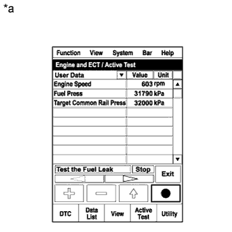
Text in Illustration *a Reference
(Active Test operation)
Enter the following menus: Powertrain / Engine and ECT / Active Test / Test the Fuel Leak.*2
-
Perform the following test 5 times with on/off intervals of 10 seconds: Active Test / Test the Fuel Leak.*3
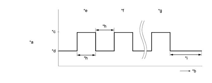
Text in Illustration *a Active Test operation *b Time *c ON *d OFF *e 1st time *f 2nd time *g 5th time *h 10 seconds *i 3 minutes or more - - -
Allow the engine to idle for 3 minutes or more after performing the Active Test for the 5th time.
-
Enter the following menus: Powertrain / Engine and ECT / DTC.
-
Read Current DTCs.
-
If no DTCs are output, air bleeding is completed.
-
If DTCs are output, perform the following procedure.
-
-
Clear the DTCs Click here.
-
Repeat steps *1 to *3.
-
Enter the following menus: Powertrain / Engine and ECT / DTC.
-
Read Current DTCs.
OK No DTCs are output
-
-
INSPECT FOR FUEL LEAK
-
Perform the Active Test.
-
Replace the normal DLC3 cable (12 V specification) for the intelligent tester with the 24 V DLC3 cable.
Note
Be sure to use the 24 V DLC3 cable when connecting the intelligent tester to the DLC3. Using the normal DLC3 cable (12 V specification) will cause damage to the tester.
-
Connect the intelligent tester to the DLC3.
-
Start the engine.
-
Turn the intelligent tester on.
-
Enter the following menus: Powertrain / Engine and ECT / Active Test.
-
Perform the Active Test.
Tester Display Test Part Control Range Diagnostic Note Test the Fuel Leak Pressurizes common rail interior and checks for fuel leaks Stop or Start
-
The fuel pressure inside the common rail is increased to a specified value and the engine speed is increased to 2000 rpm when Start is selected
-
The above conditions are preserved while the control parameter of the test is Start
-
-
-
Check for leaks from the fuel system while performing the Active Test (with a fuel pressure applied).
-