FUEL INJECTOR REMOVAL

-
CHECK ID CODE
-
Check that each injection compensation code registered in the injector assembly installed on each cylinder matches the one registered in the ECM Click here.
-
If any of the codes do not match, follow the procedure below to correct the registration details and recheck the symptom.
-
Correct the registration details by following the procedure in "INPUT INJECTOR COMPENSATION CODE(S) INTO ECM" Click here.
-
After correcting the registration details, check if the same symptom occurs as when the vehicle was brought in.
Tech Tips
If the same symptom does not occur, the symptom may be caused by errors in injection compensation code registration.
-
-
-
PRECAUTION
Note
-
After turning the ignition switch off, waiting time may be required before disconnecting the cable from the battery terminal. Therefore, make sure to read the disconnecting the cable from the battery terminal notice before proceeding with work Click here.
-
Do not allow dirt and water to enter parts.
-
Make sure that there is no dirt at the connections before installing parts.
-
Air enters the fuel pipe when installing the fuel filter case. Thoroughly purge air from the fuel pipe after installation.
-
-
DISCONNECT CABLE FROM NEGATIVE BATTERY TERMINAL
Note
When disconnecting the cable, some systems need to be initialized after the cable is reconnected Click here.
-
TILT UP CAB
CAUTION:
-
Make sure that the vehicle is on a level surface before tilting the cab up.
-
Make sure that all the doors are closed before tilting the cab up.
-
Make sure that nobody is inside or near the cab when tilting it up.
-
Be sure to have 2 people tilt the cab up when a heavy object such as a roof rack or cargo carrier is installed to the cab.
-
Be sure to remove anything set on top of the cab before tilting it up.
-
Make sure that the cab is securely locked in place after it is tilted up.
-
Make sure that there are no tools, cloths, etc. left in the engine room before tilting the cab back down.
-
Make sure that the cab is securely locked in place after tilting it back down.
-
-
REMOVE EGR COOLER SUB-ASSEMBLY
-
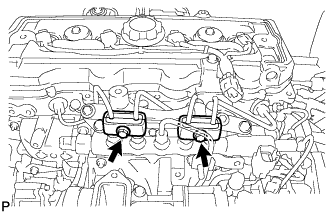
REMOVE HARNESS BRACKET
-
Disconnect each wire harness and clamp.
-
Remove the bolt and harness bracket.
-
-
REMOVE ENGINE OIL LEVEL DIPSTICK GUIDE
-
Remove the engine oil level dipstick.
-
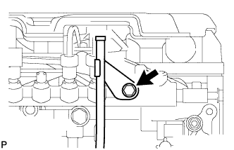
Remove the bolt and engine oil level dipstick guide.
-
Remove the O-ring from the engine oil level dipstick guide.
-
-
REMOVE CYLINDER HEAD COVER SUB-ASSEMBLY
-
Remove the 2 bolts, 2 cylinder head cover stays and cylinder head cover sub-assembly.
-
-
REMOVE NO. 2 CYLINDER HEAD COVER SUB-ASSEMBLY
-

Disconnect the 4 connectors and remove the bolt and wire harness.
-
Remove the cylinder head cover cushion rubber from the No. 2 cylinder head cover sub-assembly.
-
Remove the 2 bolts, 2 cylinder head cover cushions and 2 spacers from the No. 2 cylinder head cover sub-assembly.
-
Remove the cylinder head cover gasket and No. 2 cylinder head cover sub-assembly.
-
Remove the 4 No. 2 cylinder head cover gaskets from the 4 injector assemblies.
-
-
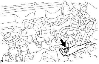
REMOVE FUEL SUPPORT
-
Remove the 2 bolts and 2 injection pipe clamps.
-
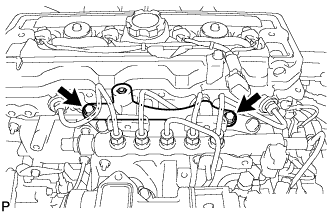
Remove the 2 bolts and fuel support.
-
-
REMOVE INJECTION PIPE SUB-ASSEMBLY
-
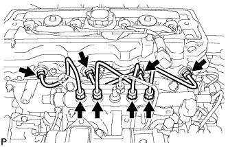
Using a 17 mm union nut wrench, loosen the 8 union nuts and remove the injection pipe sub-assembly.
-
-
REMOVE INJECTOR ASSEMBLY
Note
Make sure that no foreign matter or water enters the parts during the procedure.
-
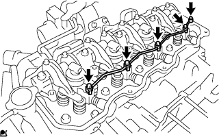
Remove the 5 hollow screws and 5 gaskets, and then remove the nozzle leakage pipe.
Tech Tips
-
After removing the nozzle leakage pipe, put it in a plastic bag to prevent foreign matter from contaminating the injector assemblies.
-
The leakage pipe can be twisted easily. Use care when handling the pipe.
-
-
Using a small screwdriver, remove the 4 nozzle holder seals.
-

Remove the 4 nozzle holder clamp bolts and 4 nozzle holder clamps.
Note
Arrange the nozzle holder clamps and bolts in the correct order.
-
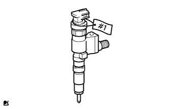
Remove the 4 injector assemblies.
Note
-
Arrange the injectors in the correct order.
-
Attach tags to identify the cylinder (#1 to #4) to the injector assemblies so that each injector assembly can be inserted into the correct cylinder during reinstallation.
-
-
Remove the gasket from each injector assembly.
-
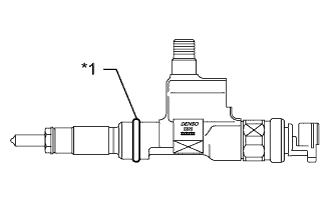
Text in Illustration *1 O-ring Remove the O-ring from each injector assembly.
-
-
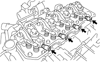
REMOVE INJECTION NOZZLE SEAT GASKET
-
Remove the 4 injection nozzle seat gaskets from the cylinder head.
-