FUEL SUPPLY PUMP REMOVAL

-
REMOVE ENGINE UNDER COVER
-
DISCONNECT CABLE FROM NEGATIVE BATTERY TERMINAL
-
DRAIN ENGINE COOLANT
CAUTION:
Do not loosen the radiator drain cock plug and engine drain plug while the engine and radiator are still hot. Pressurized, hot engine coolant and steam may be released and cause serious burns.
-
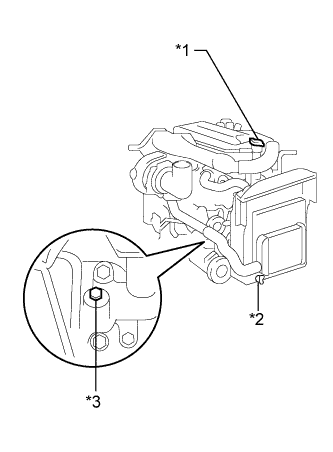
Text in Illustration *1 Radiator Cap Sub-assembly *2 Radiator Drain Cock Plug *3 Engine Drain Plug Loosen the radiator drain cock plug and engine drain plug.
-
Remove the radiator cap sub-assembly, then drain the coolant.
-
Close the radiator drain cock plug.
-
Tighten the engine drain plug.
- Torque:
- 27 N*m { 275 kgf*cm, 20 ft.*lbf, for the engine drain plug }
-
-
SET NO. 1 CYLINDER TO TDC/COMPRESSION
-
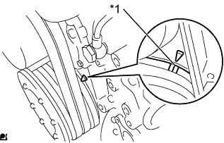
Text in Illustration *1 Timing Mark Set the No. 1 cylinder to TDC/compression.
Tech Tips
-
Make sure that there is free play in the No. 1 cylinder rocker arms and that there is no free play in the No. 4 cylinder rocker arms.
-
If not, turn the crankshaft 1 revolution (360°) to set the No. 1 cylinder to TDC/compression.
-
-
-
REMOVE ENGINE SIDE COVER SUB-ASSEMBLY LH
-
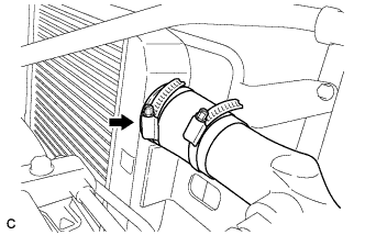
REMOVE NO. 2 INTAKE PIPE
-

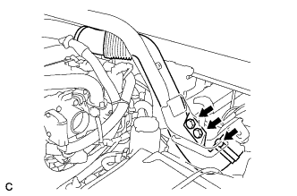
Remove the 3 bolts, loosen the 2 hose bands, and remove the No. 2 intake pipe and No. 1 air hose.
-
-
REMOVE NO. 1 AIR HOSE
-
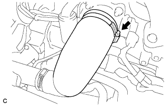
Remove the 2 bolts and hose clamp, and then remove the No. 1 air hose.
-
-
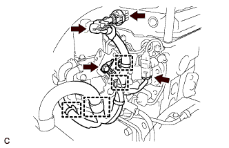
REMOVE NO. 1 INTAKE AIR PIPE WITH NO. 4 AIR HOSE
-
Disconnect the hose band.
-

Remove the bolt.
-

Disconnect the turbo pressure sensor connector and wire harness clamp, and remove the bolt.
-
Loosen the hose band and remove the No. 1 intake air pipe with No. 4 air hose.
-
-
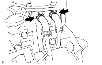
REMOVE EGR COOLER SUB-ASSEMBLY
-
Disconnect the water by-pass hose.
-
Remove the 6 bolts, EGR cooler sub-assembly, bracket and 2 gaskets.
-
-
REMOVE WIRE HARNESS AND CONNECTORS
-
Disconnect the 3 connectors, 4 wire harness clamps and bolt.
-
-
REMOVE EGR VALVE BRACKET
-

Remove the 4 bolts and bracket.
-
-
REMOVE WATER BY-PASS PIPE SUB-ASSEMBLY
-
Disconnect the 2 hoses from the EGR valve assembly.
-
Disconnect the 3 wire harness clamps.
-
Remove the 3 bolts, 2 union bolts and 4 gaskets, and separate the water by-pass pipe sub-assembly.
-
-
REMOVE DIESEL THROTTLE BODY
-
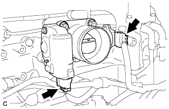
Disconnect the 2 diesel throttle body connectors.
-
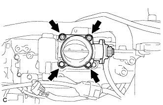
Remove the 2 bolts, 2 nuts and diesel throttle body.
-
-
REMOVE VENTURI ASSEMBLY
-
Remove the bolt and bracket from the venturi assembly.
-
Remove the 4 bolts, 2 nuts and venturi assembly from the intake manifold.
-
-
DISCONNECT FUEL HOSE
-
Disconnect the 2 fuel hoses.
-
-
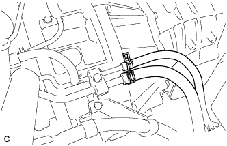
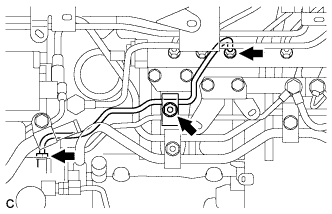
REMOVE FUEL PIPE SUB-ASSEMBLY
-
Remove the 2 bolts and nut, and then remove the 3 fuel pipe clamps.
-
Remove the union bolt and gaskets, and then remove the fuel pipe sub-assembly.
-
-
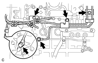
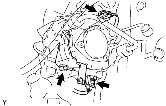
REMOVE FUEL FILTER TO INJECTION PUMP FUEL PIPE
-
Disconnect the wire harness connector.
-
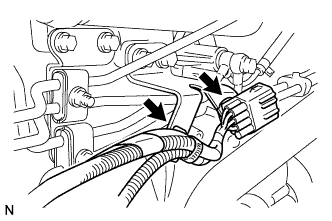
Disconnect the 2 wire harness clamps.
-
Remove the nut and fuel pipe clamp.
-
Using a union nut wrench (17 mm), loosen the 2 union nuts.
-
Remove the fuel filter to injection pump fuel pipe.
-
-
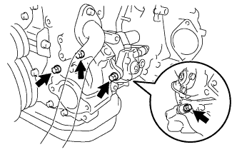
REMOVE FUEL RETURN PIPE SUB-ASSEMBLY
-

Remove the 2 union bolts and 5 gaskets.
-
Remove the fuel return pipe sub-assembly.
-
-
REMOVE CRANKSHAFT POSITION SENSOR
-
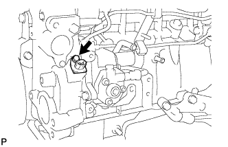
Remove the bolt and crankshaft position sensor.
-
Remove the O-ring from the crankshaft position sensor.
-
-
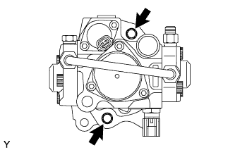
REMOVE SUPPLY PUMP ASSEMBLY
-
Disconnect the 2 connectors.
-
Remove the bolt, and then separate the holder clip.
-
Remove the 4 bolts and the supply pump assembly.
-
Remove the O-ring from the timer cover.
-
-
REMOVE INJECTION PUMP DRIVE GEAR
-
Clamp the injection pump assembly in a vise.
-
Remove the 2 bolts and the timer cover.
-
Remove the O-ring from the timer cover.
-

Remove the nut, injection pump drive gear and crankshaft angle sensor plate.
-