FUEL SUPPLY PUMP REMOVAL

-
REMOVE ENGINE UNDER COVER
-
DISCONNECT CABLE FROM NEGATIVE BATTERY TERMINAL
Note
When disconnecting the cable, some systems need to be initialized after the cable is reconnected Click here.
-
DRAIN ENGINE COOLANT
CAUTION:
Do not remove the radiator cap sub-assembly while the engine and radiator are still hot. Pressurized, hot engine coolant and steam may be released and cause serious burns.
-
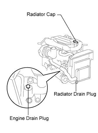
Loosen the radiator drain cock plug and engine drain plug.
-
Remove the radiator cap, then drain the coolant.
-
Close the radiator drain cock plug.
-
Tighten the engine drain plug.
- Torque:
- 27 N*m { 275 kgf*cm, 20 ft.*lbf, for the engine drain plug }
-
-
SET NO. 1 CYLINDER TO TDC/COMPRESSION
-
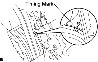
Set the No. 1 cylinder to TDC/compression.
Tech Tips
Make sure that there is free play in the No. 1 cylinder rocker arms and that there is no free play in the No. 4 cylinder rocker arms.
-
-
REMOVE ENGINE SIDE COVER SUB-ASSEMBLY LH
-
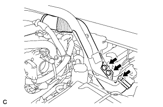
REMOVE NO. 2 INTAKE PIPE
-

Remove the 3 bolts, loosen the 2 bands, and remove the No. 2 intake pipe.
-
-
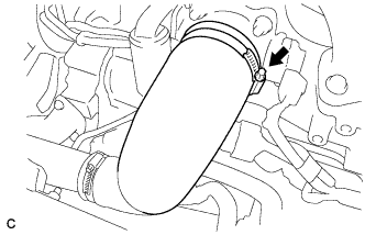
REMOVE NO. 1 AIR HOSE
-
Remove the 2 bolts and hose clamp, and then remove the No. 1 air hose.
-
-
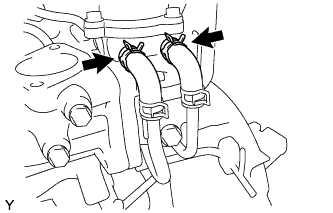
REMOVE NO. 1 INTAKE AIR PIPE WITH NO. 4 AIR HOSE
-
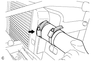
Disconnect the hose band.
-

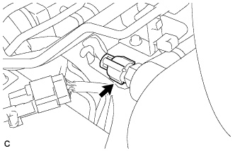
Remove the bolt.
-
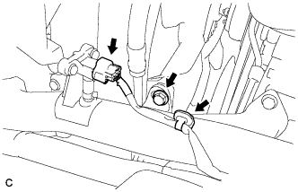
Disconnect the turbo pressure sensor connector and wire harness clamp, and remove the bolt.
-
Disconnect the intake air temperature sensor connector.
-
Disconnect the hose band, and remove the No. 1 intake air pipe with No. 4 air hose.
-
-
REMOVE EGR COOLER SUB-ASSEMBLY
-
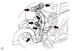
Separate the water by-pass hose.
-
Remove the 6 bolts and EGR cooler.
-
-
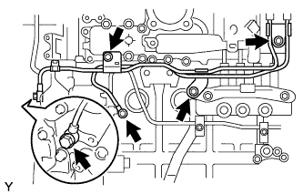
REMOVE WIRE HARNESS AND CONNECTORS
-
Disconnect the 3 connectors, 3 connector clamps and bolt.
-
-
REMOVE EGR VALVE BRACKET
-

Remove the 4 bolts and bracket.
-
-
REMOVE WATER BY-PASS PIPE SUB-ASSEMBLY
-
Disconnect the hoses from the EGR valve assembly.
-
Remove the 3 bolts, 2 union bolts, and 4 gaskets and separate the water by-pass pipe sub-assembly.
-
-
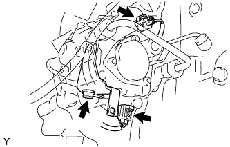
REMOVE DIESEL THROTTLE BODY
-
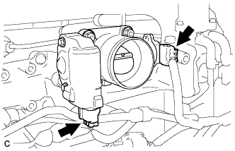
Disconnect the 2 diesel throttle body connectors.
-
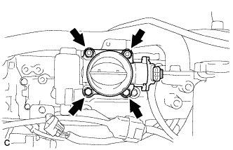
Remove the 2 bolts, 2 nuts and diesel throttle body.
-
-
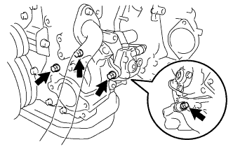
REMOVE VENTURI ASSEMBLY
-
Remove the 4 bolts, 2 nuts and venturi from the intake manifold.
-
-
DISCONNECT FUEL HOSE
-
Disconnect the 2 fuel hoses.
-
-
REMOVE FUEL PIPE SUB-ASSEMBLY
-
Remove the 2 bolts and nut, and then remove the 3 fuel pipe clamps.
-
Remove the union bolt and gaskets, and then remove the fuel pipe sub-assembly.
-
-
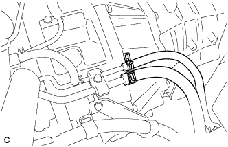
REMOVE FUEL FILTER TO INJECTION PUMP FUEL PIPE
-
Separate the wire harness connector.
-
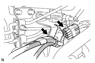
Separate the 2 wire harness clamps.
-
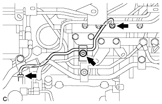
Remove the nut and fuel pipe clamp.
-
Using a union nut wrench (17 mm), loosen the 2 union nuts.
-
Remove the fuel filter to injection pump fuel pipe.
-
-
REMOVE FUEL RETURN PIPE SUB-ASSEMBLY
-

Remove the 2 union bolts and 5 gaskets.
-
Remove the fuel return pipe sub-assembly.
-
-
REMOVE CRANKSHAFT POSITION SENSOR
-
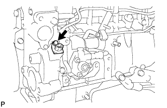
Remove the bolt and crankshaft position sensor.
-
-
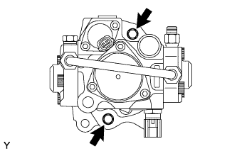
REMOVE SUPPLY PUMP ASSEMBLY
-
Separate the 2 connectors.
-
Remove the bolt, and then separate the holder clip.
-
Remove the 4 bolts and the supply pump assembly.
-
Remove the O-ring from the timer cover.
-
-
REMOVE INJECTION PUMP DRIVE GEAR
-
Clamp the injection pump assembly in a vise.
-
Remove the 2 bolts and the timer cover.
-
Remove the O-ring from the timer cover.
-

Remove the nut, injection pump drive gear and crankshaft angle sensor plate.
-